
Related Manuals for Wilo American-Marsh Pumps SXT-6"X6"


Summary of Contents for Wilo American-Marsh Pumps SXT-6"X6"
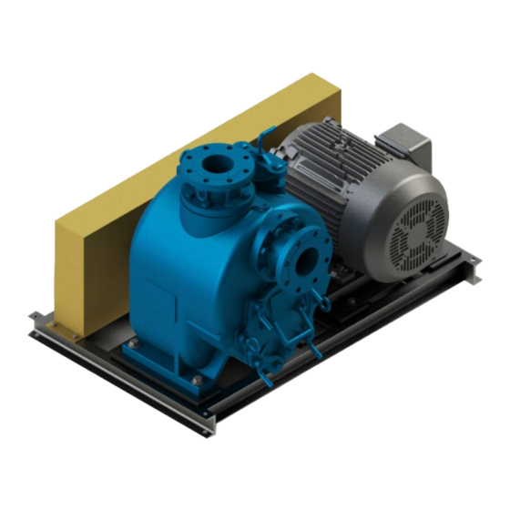
- Page 1 490 Series SXT 6”x6” Self-Priming Pumps Installation and Operating Manual *077-0242-000*...
-
Page 2: Table Of Contents
TABLE OF CONTENTS INTRODUCTION ..........................3 SAFETY SECTION A ......................... 5 INSTALLATION SECTION B ......................6 Pump Dimensions ....................... 6 PREINSTALLATION INSPECTION ....................7 POSITIONING PUMP ........................7 Lifting ..........................7 Mounting ..........................7 Clearance ........................... 7 RECOMMENDED PROCEDURE FOR BASE PLATE INSTALLATION & FINAL FIELD ALIGNMENT ......8 SUCTION AND DISCHARGE PIPING .................. - Page 3 Liquid Temperature And Overheating ................18 Strainer Check ........................19 Pump Vacuum Check ....................... 19 STOPPING ..........................19 Cold Weather Preservation ....................19 BEARING TEMPERATURE CHECK .................... 20 TROUBLESHOOTING SECTION D ....................20 PREVENTIVE MAINTENANCE ....................22 PERFORMANCE CURVE ......................24 ILLUSTRATION ........................
-
Page 4: Introduction
INTRODUCTION Thank You for purchasing an American-Marsh Pump. Read this manual carefully to learn how to safely install and operate your pump. Failure to do so could result in personal injury or damage to the pump. Because pump installations are seldom identical, this manual cannot possibly provide detailed instructions and precautions for every aspect of each specific application. - Page 5 HAZARD AND INSTRUCTION DEFINITIONS The following are used to alert maintenance personnel to procedures which require special attention, to those which could damage equipment, and to those which could be dangerous to personnel: HAZARD AND INSTRUCTION DEFINITIONS The following are used to alert maintenance personnel to procedures which require special attention, to those which could damage equipment, and to those which could be dangerous to personnel: DANGER: Immediate hazards which WILL result in severe personal injury or death.
-
Page 6: Safety Section A
SAFETY SECTION A This information applies to the 490 Series SXT 6”x6” pumps. AMP has no control over or particular knowledge of the power source which will be used. Refer to the manual accompanying the power source before attempting to begin operation. This manual will alert personnel to known procedures which require special attention, to those which could damage equipment, and to those which could be dangerous to personnel. -
Page 7: Installation Section B
INSTALLATION SECTION B Review all SAFETY information in Section A. Since pump installations are seldom identical, this section offers only general recommendations and practices required to inspect, position, and arrange the pump and piping. Most of the information pertains to a standard static lift application where the pump is positioned above the free level of liquid to be pumped. -
Page 8: Preinstallation Inspection
PREINSTALLATION INSPECTION The pump assembly was inspected and tested before shipment from the factory. Before installation, inspect the pump for damage which may have occurred during shipment. Check as follows: Inspect the pump for cracks, dents, damaged threads, and other obvious damage. b. -
Page 9: Recommended Procedure For Base Plate Installation & Final Field Alignment
of the cover and easy access to the pump interior. A minimum clearance of 11 inches (279,4 mm) must be maintained to permit removal of the cover. RECOMMENDED PROCEDURE FOR BASE PLATE INSTALLATION & FINAL FIELD ALIGNMENT NEW GROUTED BASE PLATES The pump foundation should be located as close to the source of the fluid to be pumped as practical. - Page 10 Check initial alignment. If the pump and motor were removed from the base plate proceed with step 5 first, then the pump and motor should be reinstalled onto the base plate using American-Marsh’s Factory Preliminary Alignment Procedure, and then continue with the following. As described above, pumps are given a preliminary alignment at the factory.
-
Page 11: Suction And Discharge Piping
SUCTION AND DISCHARGE PIPING Pump performance is adversely affected by increased suction lift, discharge elevation, and friction losses. See the performance curve and operating range shown in SECTION E to be sure your overall application allows pump to operate within the safe operation range. Materials Either pipe or hose maybe used for suction and discharge lines;... -
Page 12: Sealing
total area of the openings in the strainer is at least three or four times the cross section of the suction line, and that the openings will not permit passage of solids larger than the solids handling capability of the pump. This pump is designed to handle up to 3-inch (76,2 mm) diameter spherical solids. -
Page 13: Discharge Lines
Figure 2. Recommended Minimum Suction Line Submergence vs. Velocity DISCHARGE LINES Siphoning DO NOT terminate the discharge line at a level lower than that of the liquid being pumped unless a siphon breaker is used in the line. Otherwise, a siphoning action causing damage to the pump could result. -
Page 14: Bypass Lines
Bypass Lines Self‐priming pumps are not air compressors. During the priming cycle, air from the suction line must be vented to atmosphere on the discharge side. If the discharge line is open, this air will be vented through the discharge. However, if a check valve has been installed in the discharge line, the discharge side of the pump must be opened to atmospheric pressure through a bypass line installed between the pump discharge and the check valve. -
Page 15: Air Release Valve Installation
Some leakage (1 to 5 gallons [3.8 to 19 liters] per minute) will occur when the valve is fully closed. Be sure the bypass line is directed back to the wet well or tank to prevent hazardous spills * Consult the manual accompanying the Air Release Valve for additional information on valve installation and performance. -
Page 16: Alignment
independent bleeder line directed back to the wet well. If multiple Air Release Valves are installed in a system, DO NOT direct bleeder lines to a common manifold pipe. ALIGNMENT The alignment of the pump and its power source is critical for trouble‐free mechanical operation. In either a flexible coupling or V‐belt driven system, the driver and pump must be mounted so that their shafts are aligned with and parallel to each other. -
Page 17: Drive Belts
Align non‐spider type couplings by using a feeler gauge or taper gauge between the coupling halves every 90°. The coupling is in alignment when the hubs are the same distance apart at all points (see Figure 5). Check parallel adjustment by laying a straightedge across both coupling rims at the top, bottom, and side. -
Page 18: Operation Section C
tensioning will cause belt slippage. Always keep belts free from dirt, grease, oil and other foreign material which may cause slippage. OPERATION SECTION C Review all SAFETY information in Section A. Follow the instructions on all tags, labels and decals attached to the pump. This pump is designed to handle liquids containing large, entrained solids and slurries. -
Page 19: Operation
source rotation before further troubleshooting. If an electric motor is used to drive the pump, remove V‐belts, couplings, or otherwise disconnect the pump from the motor before checking motor rotation. Operate the motor independently while observing the direction of the motor shaft, or cooling fan. If rotation is incorrect on a three‐phase motor, have a qualified electrician interchange any two of the three phase wires to change direction. -
Page 20: Strainer Check
disengaged to be ejected with great force. After the pump completely cools, drain the liquid from the pump by removing the casing drain plug. Use caution when removing the plug to prevent injury to personnel from hot liquid. As a safeguard against rupture or explosion due to heat, this pump is equipped with a pressure relief valve which will open if vapor pressure within the pump casing reaches a critical point. -
Page 21: Bearing Temperature Check
In below freezing conditions, drain the pump to prevent damage from freezing. Also, clean out any solids by flushing with a hose. Operate the pump for approximately one minute; this will remove any remaining liquid that could freeze the pump rotating parts. If the pump will be idle for more than a few hours, or if it has been pumping liquids containing a large amount of solids, drain the pump, and flush it thoroughly with clean water. - Page 22 TROUBLE POSSIBLE CAUSE PROBABLE REMEDY PUMP FAILS TO Not enough liquid in casing. Add liquid to casing. See PRIMING. PRIME Suction check valve contaminated or Clean or replace check valve. damaged. Air leak in suction line. Correct leak. Lining of suction hose collapsed. Replace suction hose.
-
Page 23: Preventive Maintenance
EXCESSIVE NOISE Cavitation in pump. Reduce suction lift and/or friction losses in suction line. Record vacuum and pressure gauge readings and consult local representative or factory. Pumping entrained air. Locate and eliminate source of air bubble. Pump or drive not securely mounted. Secure mounting hardware. - Page 24 Preventive Maintenance Schedule Service Interval* Item Daily Weekly Monthly Semi‐ Annually Annually General Condition (Temperature, Unusual Noises or Vibrations, Cracks, Leaks, Loose Hardware, Etc.) Pump Performance (Gauges, Speed, Flow) Bearing Lubrication Seal Lubrication (And Packing Adjustment, If So Equipped) V‐Belts (If So Equipped) Air Release Valve Plunger Rod (If So Equipped) Front Impeller Clearance (Wear Plate) Rear Impeller Clearance (Seal Plate)
-
Page 25: Performance Curve
PUMP MAINTENANCE AND REPAIR SECTION E MAINTENANCE AND REPAIR OF THE WEARING PARTS OF THE PUMP WILL MAINTAIN PEAK OPERATING PERFORMANCE. PERFORMANCE CURVE * STANDARD PERFORMANCE FOR PUMP MODEL SXT-6”X6” Based on 70°F (21° C) clear water at sea level with minimum suction lift. Since pump installations are seldom identical, your performance may be different due to such factors as viscosity, specific gravity, elevation, temperature, and impeller trim. -
Page 26: Illustration
ILLUSTRATION Figure 1. Pump Model SXT-6”X6” IOM 490 SXT 6”X6”_0223... -
Page 27: Parts List
PARTS LIST Pump Model SXT-6”X6” Contact AMP to verify part numbers. PART NAME PART NAME PART NAME Cap screw Pipe Plug Mechanical Seal Assembly Lock Washer Lifting Bolt / Eye Bolt Seal Plate Suction Flange Pump Casing Seal Plate Gasket Pipe Plug Cap screw Inboard Oil Seal... -
Page 28: Pump And Seal Disassembly And Reassembly
PUMP AND SEAL DISASSEMBLY AND REASSEMBLY Review all SAFETY information in Section A. Follow the instructions on all tags, label and decals attached to the pump. This pump requires little service due to its rugged, minimum‐maintenance design. However, if it becomes necessary to inspect or replace the wearing parts, follow these instructions which are keyed to the illustration (see Figure 1) and the accompanying parts lists. -
Page 29: Suction Check Valve Removal
attempting to service the pump, remove the pump casing drain plug (43) and drain the pump. Clean and reinstall the drain plug. Remove the hand nuts (34) and studs (35) and pry the back cover and assembled wear plate from the pump casing (28). -
Page 30: Impeller Removal
Figure 2. Loosening Impeller Figure 3. Rotating Assembly Tool (Figure 1) Remove the hardware (62 and 63) securing the rotating assembly to the pump casing. Separate the rotating assembly by pulling straight away from the pump casing. Tie and tag the rotating assembly adjusting flat washers (58) for ease of reassembly. -
Page 31: Shaft And Bearing Removal And Disassembly
Slide the integral shaft sleeve and rotating portion of the seal off the shaft as a unit. Use a pair of stiff wires with hooked ends to remove the stationary element and seat. An alternate method of removing the stationary seal components is to remove the hardware (57 and 59) and separate the seal plate (52) and gasket (53) from the bearing housing (44). -
Page 32: Shaft And Bearing Reassembly And Installation
The bearing tolerances provide a tight press fit onto the shaft and a snug slip fit into the bearing housing. Replace the bearings, shaft, or bearing housing if the proper bearing fit is not achieved. If bearing replacement is required, remove the outboard bearing snap ring (70), and use a bearing puller to remove the bearings from the shaft. -
Page 33: Seal Installation
When installing the bearings onto the shaft, never press or hit against the outer race, balls, or ball cage. Press only on the inner race. Secure the outboard bearing on the shaft with the bearing snap ring (70). Slide the shaft and assembled bearings into the bearing housing until the retaining ring on the outboard bearing seats against the bearing housing. - Page 34 Figure 4. Cartridge Seal Assembly This seal is not designed for operation at temperatures above 160°F (71°C). Do not use at higher operating temperatures If the seal plate (52) was removed, install the seal plate gasket (53). Position the seal plate over the shaft and secure it to the bearing housing with the hardware (57 and 59).
- Page 35 Figure 5. Seal Partially Installed Figure 6. Seal Fully Installed Continue to screw the impeller onto the shaft. This will press the stationary seat into the seal plate bore. NOTE A firm resistance will be felt as the impeller presses the stationary seat into the seal plate bore. As the stationary seat becomes fully seated, the seal spring compresses, and the shaft sleeve will break the nylon shear ring.
-
Page 36: Impeller Installation And Adjustment
seal plate bore until it seats squarely against the bore shoulder. A push tube made from a piece of plastic pipe would aid this installation. The I.D. of the pipe should be slightly larger than the O.D. of the shaft sleeve. Slide the rotating portion of the seal (consisting of the integral shaft sleeve, spring centering washer, spring, bellows and retainer, and rotating element) onto the shaft until the seal faces contact. -
Page 37: Suction Check Valve Installation
To set the impeller and wear plate clearance, refer to Back Cover and Wear Plate Installation and Adjustment. Suction Check Valve Installation (Figure 1) Inspect the check valve assembly (8~13), replace it if badly worn. NOTE The check valve assembly must be replaced as a complete unit. Individual parts are not sold separately. - Page 38 Figure 7. Installing and Adjusting Back Cover Screw the four adjusting studs (35) into the tapped holes in the back cover plate until they are just flush with the machined surface on the back side of the cover plate. Align the back cover plate over the two eye bolts (32) and slide it into the pump casing. Use two hand nuts (34) on diagonally opposing studs to press the back cover into the pump casing until the wear plate just touches the impeller when the shaft is turned by hand.
-
Page 39: Pressure Relief Valve Maintenance
Allow an installed pump to completely cool before draining liquid from the pump casing. Remove the back cover. Remove the rotating assembly adjusting shims, then reinstall the hardware securing the rotating assembly to the pump casing. Perform the back cover adjustment procedure described above to obtain the proper face clearance. -
Page 40: Bearings
Bearings (Figure 1) The bearing housing has not been lubricated from the factory. Lubrication must be added to the seal and bearing sump prior to running. Check the oil level regularly through the sight gauge (64, the lower one) and maintain it at the middle of the gauge. When lubrication is required, add SAE No. 30 non‐detergent oil through the hole for the air vent (46). -
Page 41: Warranty
WARRANTY American-Marsh Pumps guarantees that only high-quality materials are used in the construction of our pumps and that machining and assembly are carried out to high standards. The pumps are guaranteed against defective materials and/or faulty craftsmanship for a period of one (1) year from the date of shipment unless specifically stated otherwise.
Need help?
Do you have a question about the American-Marsh Pumps SXT-6"X6" and is the answer not in the manual?
Questions and answers