
Related Manuals for Wilo STRATOS GIGA


Summary of Contents for Wilo STRATOS GIGA
- Page 1 Wilo-Stratos GIGA en Installation and operating instructions Notice de montage et de mise en service es Instrucciones de instalación y funcionamiento...
- Page 2 Fig. 1: IF-Modul Fig. 2: Fig. 3: ” ” ” ” Option IF-/LON-Modul IF-Modul LON-Modul M12x1.5...
- Page 3 Fig. 4: max. 20 A RK5 Single pump MA Twin pump SL Twin pump external supply min. 12 V DC / 10 mA max. 250 V AC / 1 A pressure sensor external value 10 V / 20 mA external off (switch) external off (switch) pump swamp (button)
- Page 4 Fig. 5: [ft] [1/min] Δp Δp 1,0 1,5 2,8 3,2 [ft] [1/min] Δp Δp [mA] 10,4 Fig. 6:...
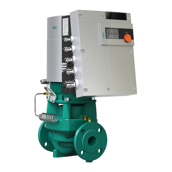
- Page 5 Fig. 7: Stratos GIGA...
- Page 7 Installation and operating instructions Notice de montage et de mise en service Instrucciones de instalación y funcionamiento...
-
Page 8: Table Of Contents
Setting the control mode ........................... 47 Maintenance ............................48 10.1 Air supply ................................50 10.2 Maintenance work ..............................50 Faults, causes and remedies ......................57 11.1 Mechanical faults ..............................57 11.2 Error table ................................58 11.3 Acknowledging errors ............................59 Spare parts ............................65 Disposal ...............................65 WILO SE 06/2011... -
Page 9: General Notes
The user can be exposed to (severe) injury. 'Warning' refers that harm to the user when the user is neglecting the procedure. CAUTION! The product is at risk of damage. 'Caution' refers to the product when the user is neglecting the procedures. Installation and operating instructions Wilo-Stratos GIGA... -
Page 10: Qualified Personnel
• National statutory provisions are to be complied with. • Highly flammable materials are always to be kept at a safe distance from the product. • Danger from electrical current must be eliminated. National Electrical Codes, local codes and regulations must be followed. WILO SE 06/2011... -
Page 11: Safety Precautions For Installation And Maintenance Work
• Use the original packaging for this, or choose equivalent packag- ing. Use the provided transport eyes for lifting. • Check the transport eyes before use for damage and secure fixa- tion. Installation and operating instructions Wilo-Stratos GIGA... -
Page 12: Transport For Installation/Dismantling Purposes
(Fig. 7, Item 20a). Fig. 8: Transporting the pump Fig. 9: Transport of the motor impeller unit WILO SE 06/2011... -
Page 13: Intended Use
Intended use Purpose The glanded pumps of the Stratos GIGA series are intended for use as circulation pumps in building services. Fields of application They may be used for: •... -
Page 14: Product Information
These can cause serious cuts, crushing injuries and bruises. • Do not open the motor! • Only allow Wilo customer service to dismantle and install the motor flange and the end shield for maintenance and repair work. CAUTION! Danger of property damage! Unpermitted substances in the fluid can destroy the pump. -
Page 15: Technical Data
The respective manufacturer's instructions are to be observed. • The fluid must be free of sediments. • Wilo's approval must be obtained for use of other media. • Mixtures with a proportion of glycol of > 10% influence the Δp-v pump curve and the flow calculation. -
Page 16: Scope Of Delivery
(voltage-free). Description and function Description of the product The Wilo-Stratos GIGA high-efficiency pumps are glanded pumps with built-in power adjustment and “Electronic Commutated Motor” (ECM) technology. The pumps are designed as single-stage low- pressure centrifugal pumps with flange connection and mechanical seal. - Page 17 Electronic module Tab. 1: Arrangement of the main components The typical characteristic of the Stratos GIGA series is the jacket cool- ing of the motor. The air current is optimally conducted by the long fan cover (Fig. 10, Item 1) for cooling the motor and the electronic module.
- Page 18 English Name plates The Wilo-Stratos GIGA has three name plates: • The pump name plate (Fig. 11, Item 1) includes the serial number (Ser.-No…/…), which is, for example, required for spare parts ordering. • The electronic module name plate (electronic module = inverter or frequency converter) (Fig.
-
Page 19: Control Modes
Fig. 15: Δp-c control NOTE: For further information about setting the control mode and the asso- ciated parameters, see chapter 8 “Operation” on page 29 and chapter 9.4 “Setting the control mode” on page 47. Installation and operating instructions Wilo-Stratos GIGA... -
Page 20: Dual Pump Function/Y-Pipe Application
• Both pumps are controlled by the master pump. If one of the pumps malfunctions, the other will run according to the master's control settings. In case of a total failure of the master, the slave pump operates at emergency operation speed. WILO SE 06/2011... - Page 21 Each of the two pumps provides the configuration flow rate. The other pump is available in case of malfunction or runs after pump cycling. Only one pump runs at a time (see Fig. 15, 16 and 17). Installation and operating instructions Wilo-Stratos GIGA...
- Page 22 • This signal can be programmed on the master (or using the IR-Monitor) as an individual fault signal (ESM) or a collective fault signal (SSM) in menu <5.1.5.0>. • The contact must be made to each pump for individual fault signals. WILO SE 06/2011...
- Page 23 (former) slave will start up with the factory settings of a single pump. It will then run in Δp-c mode at approximately half the maximum delivery head. Installation and operating instructions Wilo-Stratos GIGA...
-
Page 24: Other Functions
The number of pump exercises can be seen in menu <4.2.6.0>. All faults, with the exception of warnings, that occur during the pump exercise switch the motor off. The corresponding fault code is shown on the display. WILO SE 06/2011... -
Page 25: Installation And Electrical Connection
WILO differential pressure sensor. • Default value: input In = 0-10 volts, pressure value correction = ON • When using the supplied Wilo differential pressure sensor, these settings must not be changed! Modifications are only needed if another differential pressure sensor is used. - Page 26 • Have the pump installed by qualified personnel only. • Make sure that the volume flow does not go below the minimum value Q • Calculation of Q Actual speed = 10% x Q max pump Max. speed WILO SE 06/2011...
-
Page 27: Permitted Installations Position And Change Of The Arrangement Of Components Before The Installation
The motor impeller unit can – relative to the pump housing – 4 x 90° be arranged in four different positions (each shifted by 90°). Fig. 23: Permitted installation positions with vertical motor shaft Installation and operating instructions Wilo-Stratos GIGA... - Page 28 • For optimal positioning of the pressure measuring lines, the differen- tial pressure sensor can be separated from the holder (Fig. 7, Item 6), rotated by 180° around the longitudinal axis and reinstalled. WILO SE 06/2011...
-
Page 29: Installation
Shut-off devices shall be installed in front of and behind the pump in all cases, in order to avoid having to drain the entire system when checking or replacing the pump. Fig. 24: Transport of the motor impeller unit Installation and operating instructions Wilo-Stratos GIGA... -
Page 30: Electrical Connection
• National Electrical Codes (NEC), local codes and regulations must be striclty followed. • Observe the installation and operating instructions for the acces- sories! WILO SE 06/2011... - Page 31 Installation notes Integral solid state short circuit protection does not provide branch circuit protection. Branch circuit protection must be provided in accordance with the Manufacturer Instructions, National Electrical Code and any additional local codes. Installation and operating instructions Wilo-Stratos GIGA...
- Page 32 • Suitable for use on a circuit capable of delivering not more than 5000 rms symmetrical Amperes, 480 V maximum when protected by CC, J or RK5 Class Fuses, rated 20 A. WILO SE 06/2011...
- Page 33 For details see wiring diagram (Fig. 4). Fig. 26: Control terminals • Power terminals (mains connection terminals) (Fig. 27). See following table for assignment. For details see wiring diagram (Fig. 4). Fig. 27: Power terminals (mains connection terminals) Installation and operating instructions Wilo-Stratos GIGA...
- Page 34 The terminals IN1, IN2, AUX, GND, Ext. Off and MP meet the require- ment for “isolated secondary circuits, limited voltage/limited current” (according to UL508C and EN 61800-5-1) to the mains terminals, as well as to the SBM and SSM terminals (and vice versa). WILO SE 06/2011...
-
Page 35: Operation
For additional information, see chapter 8.6.7 “Activating/deactivating access disable” on page 37. • Switches 3 and 4 permit termination of the multi-pump communica- tion. For additional information, see chapter 8.6.8 “Activating/deactivating termination” on page 37. Installation and operating instructions Wilo-Stratos GIGA... -
Page 36: Display Structure
PID control Pump is stopping Input In (external setpoint) Pump running in emergency operation activated Access disable Pump stops in emergency operation BMS (Building Management System) is DP/MP operating mode: Main/reserve active DP/MP operating mode: Parallel operation WILO SE 06/2011... -
Page 37: Symbols In Graphics/Instructions
The display will be shown for the duration of this process. Fig. 31: Display test DANGER! Danger of death! There can be electrical charges present in the display even if is switched off. • Observe general safety instructions! Installation and operating instructions Wilo-Stratos GIGA... - Page 38 <4.1.5.0>, the menu number jumps to <4.1.0.0>. NOTE: If the red button is pressed for two seconds while a “One level up” menu element is selected, the display jumps back to the status page. WILO SE 06/2011...
- Page 39 • Only have faults corrected by qualified personnel. • If in doubt, consult the manufacturer. For additional information, see chapter 11 “Faults, causes and reme- dies” on page 57 and the error table shown there. Installation and operating instructions Wilo-Stratos GIGA...
-
Page 40: Operating Instructions
If service mode is activated via DIP switch 1 menu number <5.0.0.0> ± is displayed first. (Fig. 35). 5.0.0.0 12.3 Fig. 35: Service menu mode Error case: In case of error, menu number <6.0.0.0> is displayed (Fig. 36). ± 6.0.0.0 E000 Fig. 36: Error case menu mode WILO SE 06/2011... - Page 41 Fig. 38: Setting with return to the “Selec- The selected setpoint or setting is confirmed, and the value or symbol tion/settings” menu element stops flashing. The display has returned to menu mode with the menu number unchanged. The menu number flashes. Installation and operating instructions Wilo-Stratos GIGA...
- Page 42 “Selection/setting” element type, and the stan- dard “access disable” symbol (see symbol) is hidden for the respective elements (except for <5.3.1.0>). The values and settings for these elements can now be edited. • To deactivate, return the switch to its starting position. WILO SE 06/2011...
-
Page 43: Menu Elements Reference
If, for example, the external setpoint adjustment under menu number <5.4.1.0> is set to 'OFF', the number <5.4.2.0> will be hidden. Menu number <5.4.2.0> will only be visible if menu number <5.4.1.0> has been set to 'ON'. Installation and operating instructions Wilo-Stratos GIGA... - Page 44 W 4.2.0.0 Operating data Display of operating data The operating data refer to the module currently being operated 4.2.1.0 Operating hours Sum of the pump's active hours of operation (counter can be reset by infrared interface) WILO SE 06/2011...
- Page 45 4.3.3.0 State of the SBM relay if a readi- ness/operation or “mains on” signal is present State of the SBM relay if no read- iness/operation or “mains on” signal is present Installation and operating instructions Wilo-Stratos GIGA...
- Page 46 Only displayed when BMS is active Only displayed when BMS is field bus system active Only displayed when BMS is field bus system active Gateway Only displayed when BMS is Protocol active 4.4.0.0 Device data Displays device data WILO SE 06/2011...
- Page 47 Collective readiness signal Only displayed in DP-MA mode Collective run signal Only displayed in DP-MA mode ± 5.1.7.0 External Off Individual external Off Only displayed in DP-MA mode Collective external Off Only displayed in DP-MA mode Installation and operating instructions Wilo-Stratos GIGA...
- Page 48 Setting of the value range Not displayed when IN2 = Possible values: 0...10 V/ inactive 2...10 V/0...20 mA/4...20 mA 5.5.0.0 PID parameters Settings for PID control Only displayed when PID control is active (incl. all sub- menus) WILO SE 06/2011...
- Page 49 SBM mains on signal ± 5.7.7.0 Factory setting OFF (default setting) Is not displayed when Settings are not changed by “access disable” is active. confirming. Is not displayed when build- ing management system active. Installation and operating instructions Wilo-Stratos GIGA...
-
Page 50: Commissioning
Before commissioning, the pump and module must be at ambient temperature. Filling and bleeding • Prime and bleed the system as required. CAUTION! Damage to the pump! Dry running will destroy the mechanical seal. • Make sure that the pump does not run dry. WILO SE 06/2011... - Page 51 If the pump/system is installed improperly, liquid may be ejected during commissioning. Individual components may also become loose. • Keep a safe distance from the pump during commissioning. • Wear protective clothing, protective gloves and protective goggles. Installation and operating instructions Wilo-Stratos GIGA...
-
Page 52: Double Pump Installation/Y-Pump Installation
• Make sure that the volume flow does not go below the minimum value Q • Calculation of Q Actual speed = 10% x Q max pump Max. speed WILO SE 06/2011... -
Page 53: Setting The Control Mode
In the factory settings, the D term is set to zero, since this is an appropriate setting for a number of applications. These parameters should only be changed in small increments, and the effects on the system should be monitored continuously. Para- Installation and operating instructions Wilo-Stratos GIGA... -
Page 54: Maintenance
Safety Have maintenance and repair work carried out by qualified person- nel only! It is recommended to have the pump serviced and checked by WILO Customer Service. DANGER! Danger of death! There is a mortal danger through shock when working on electrical equipment. - Page 55 Non-observance results in death or very serious injuries. • Do not open the motor! • Only allow Wilo customer service to dismantle and install the rotor for maintenance and repair work. WARNING! Danger of personal injury! Opening the motor leads to high, suddenly occurring magnetic forces.
-
Page 56: Air Supply
A visual inspection should be performed from time to time, however. If there is clearly detectable leakage, the seal must be changed. Wilo offers a repair kit which contains the necessary parts for replace- ment. Dismantling 1. Disconnect the system from the power supply and secure it against being switched on again. - Page 57 (Fig. 7, Item 5) with the holder (Fig. 7, Item 6) to be suspended at the pressure measurement lines (Fig. 7, Item 13). Disconnect the connecting cable of the differential pressure sen- sor in the electronic module. Installation and operating instructions Wilo-Stratos GIGA...
- Page 58 21. Insert a new counter ring in the lantern. 22. Carefully push the lantern over the shaft and position it in the old position or another desired angular position to the motor flange. Observe the permitted installation positions of the components WILO SE 06/2011...
- Page 59 Observe the permitted installation positions of the components when doing this (see chapter 7.1 “Permitted installation positions and change of the arrangement of components before the installa- tion” on page 21). Installation and operating instructions Wilo-Stratos GIGA...
- Page 60 44. 38. Clamp the connecting cable of the differential pressure sensor/ power cable back on if it was disconnected. 39. Open the check valves in front of and behind the pump. 40. Reset the fuse. WILO SE 06/2011...
- Page 61 Fig. 2 lead-throughs nection line of the ” Hexagon head 0.9 in (22 mm) 6/72 (8) series sensor only ” Hexagon head 1.1 in (27 mm) 8/96 (11) Tab. 2 Screw tightening torques Installation and operating instructions Wilo-Stratos GIGA...
- Page 62 NOTE: Increased bearing noise and unusual vibrations are a sign of bearing wear. Then the bearing has to be changed by Wilo customer service. WARNING! Danger of personal injury! Opening the motor leads to high, suddenly occurring magnetic forces.
-
Page 63: Faults, Causes And Remedies
Motor has bearing damage Have the pump checked by Wilo cus- tomer service or a specialized service center and serviced if necessary Installation and operating instructions Wilo-Stratos GIGA... -
Page 64: Error Table
E033 Intermediate circuit Voltage fluctuations in Check electrical installation overvoltage the mains E035 DP/MP: multiple multiple instances of Reallocate master and/or slave instances of same same identity (see chap. 9.2 on page 46) identity WILO SE 06/2011... -
Page 65: Acknowledging Errors
On the units display, the current incidence (x) as well as the maximum incidence of the error (y) are displayed in the format “x/y”. Until the error can be acknowledged, pressing the red button again will cause a return to menu mode. Installation and operating instructions Wilo-Stratos GIGA... - Page 66 • Error counter is incremented Is there a new type “A” fault? > 1 minute? Error acknowledged? Is there a new type “A” fault? Branching for error type “A” End; auto control resumes Fig. 52: Error type D, diagram WILO SE 06/2011...
- Page 67 Fig. 54: Error type B, diagram Menu number <6.0.0.0> appears steady on the display. On the units display, the current incidence (x) as well as the maximum incidence of the error (y) are displayed in the format “x/y”. Installation and operating instructions Wilo-Stratos GIGA...
- Page 68 On the value display, the remaining time until manual acknowledg- ment of the error is displayed in seconds. 6.0.0.0 • Press the red button again. The error is acknowledged, and the status page is displayed. 6.0.0.0 12.3 Fig. 56: Acknowledge error type B (X=Y) WILO SE 06/2011...
- Page 69 If the current incident (x) is the same as the maximum incidence of the 12.3 error (y), this error can be acknowledged manually. • Press the red button again. Fig. 58: Acknowledge error type C The error is acknowledged, and the status page is displayed. Installation and operating instructions Wilo-Stratos GIGA...
- Page 70 Fig. 59: Error type E, diagram Error type F (Fig. 60): Program Contents step/query • Error code is displayed • Error counter is incremented Error criterion fulfilled? Error acknowledged? End; auto control resumes Fig. 60: Error type F, diagram WILO SE 06/2011...
-
Page 71: Spare Parts
The error will be acknowledged automatically if the cause of the error is eliminated. Spare parts Spare parts may be ordered via a local specialist retailer and/or WILO- customer service. To avoid queries and incorrect orders, all data on the name plate should be submitted for each order (pump name plate Fig.
Need help?
Do you have a question about the STRATOS GIGA and is the answer not in the manual?
Questions and answers