
Related Manuals for Wilo American-Marsh 490 Series


Summary of Contents for Wilo American-Marsh 490 Series
- Page 1 A WILO BRAND 490 Series SXU 3” & 4” Self-Priming Pumps Installation and Operating Manual...
-
Page 2: Table Of Contents
TABLE OF CONTENTS INTRODUCTION ........................- 4 - SAFETY SECTION A ........................- 5 - INSTALLATION SECTION B ......................- 7 - Pump Dimensions ......................... - 7 - Outline Drawing ........................- 7 - PREINSTALLATION INSPECTION ....................- 8 - POSITIONING PUMP ........................ - Page 3 Strainer Check ........................- 19 - Pump Vacuum Check ......................- 19 - STOPPING ..........................- 19 - Cold Weather Preservation ....................- 19 - BEARING TEMPERATURE CHECK .................... - 20 - TROUBLESHOOTING SECTION D ..................... - 20 - PREVENTIVE MAINTENANCE ....................- 22 - PUMP MAINTENANCE AND REPAIR SECTION E ..............
-
Page 4: Introduction
INTRODUCTION Thank You for purchasing an American-Marsh Pump. Read this manual carefully to learn how to safely install and operate your pump. Failure to do so could result in personal injury or damage to the pump. Because pump installations are seldom identical, this manual cannot possibly provide detailed instructions and precautions for every aspect of each specific application. -
Page 5: Safety Section A
HAZARD AND INSTRUCTION DEFINITIONS The following are used to alert maintenance personnel to procedures which require special attention, to those which could damage equipment, and to those which could be dangerous to personnel: DANGER: Immediate hazards which WILL result in severe personal injury or death. These instructions describe the procedure required and the injury which will result from failure to follow the procedure. - Page 6 This pump is designed to handle most non‐volatile, non‐flammable liquids containing specified entrained solids. Do not attempt to pump volatile, corrosive, or flammable materials which may damage the pump or endanger personnel as a result of pump failure. After the pump has been positioned, make certain that the pump and all piping connections are tight, properly supported and secure before operation.
-
Page 7: Installation Section B
INSTALLATION SECTION B Review all SAFETY information in Section A. Since pump installations are seldom identical, this section offers only general recommendations and practices required to inspect, position, and arrange the pump and piping. Most of the information pertains to a standard static lift application where the pump is positioned above the free level of liquid to be pumped. -
Page 8: Preinstallation Inspection
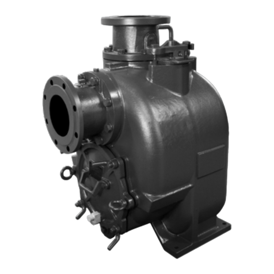
Figure 2. Pump Model SXU-4” PREINSTALLATION INSPECTION The pump assembly was inspected and tested before shipment from the factory. Before installation, inspect the pump for damage which may have occurred during shipment. Check as follows: Inspect the pump for cracks, dents, damaged threads, and other obvious damage. b. -
Page 9: Positioning Pump
POSITIONING PUMP Lifting Pump unit weights will vary depending on the mounting and drive provided. Check the shipping tag on the unit packaging for the actual weight, and use lifting equipment with appropriate capacity. Drain the pump and remove all customer‐installed equipment such as suction and discharge hoses or piping before attempting to lift existing, installed units. -
Page 10: Gauges
Lines near the pump must be independently supported to avoid strain on the pump which could cause excessive vibration, decreased bearing life, and increased shaft and seal wear. If hose‐type lines are used, they should have adequate support to secure them when filled with liquid and under pressure. -
Page 11: Suction Line Positioning
the suction inlet at a distance 1 1/2 times the diameter of the suction pipe. The baffle will allow entrained air to escape from the liquid before it is drawn into the suction inlet. If two suction lines are installed in a single sump, the flow paths may interact, reducing the efficiency of one or both pumps. -
Page 12: Discharge Lines
DISCHARGE LINES Siphoning Do not terminate the discharge line at a level lower than that of the liquid being pumped unless a siphon breaker is used in the line. Otherwise, a siphoning action causing damage to the pump could result. Valves If a throttling valve is desired in the discharge line, use a valve as large as the largest pipe to minimize friction losses. -
Page 13: Automatic Air Release Valve
If the installation involves a flooded suction such as a below‐ground lift station. A pipe union and manual shut‐off valve may be installed in the bleed line to allow service of the valve without shutting down the station, and to eliminate the possibility of flooding. If a manual shut‐off valve is installed anywhere in the air release piping, it must be a full‐opening ball type valve to prevent plugging by solids. -
Page 14: Alignment
Figure 4. Typical Automatic Air Release Valve Installation Connect the valve outlet to a bleed line which slopes back to the wet well or sump. The bleed line must be the same size as the outlet opening or larger, depending on which Air Release Valve is being used. -
Page 15: Coupled Drives
When checking alignment, disconnect the power source to ensure that the pump will remain inoperative. Adjusting the alignment in one direction may alter the alignment in another direction. check each procedure after altering alignment. Coupled Drives When using couplings, the axis of the power source must be aligned to the axis of the pump shaft in both the horizontal and vertical planes. -
Page 16: Operation Section C
Figure 7. Alignment of V‐Belt Driven Pumps ALIGNED: MISALIGNED: MISALIGNED: SHAFTS PARALLEL AND SHAFTS NOT PARALLEL SHAFTS NOT IN LINE SHEAVES IN LINE Tighten the belts in accordance with the belt manufacturer's instructions. If the belts are too loose, they will slip; if the belts are too tight, there will be excessive power loss and possible bearing failure. -
Page 17: Priming
Pump speed and operating conditions must be within the performance range shown in SECTION E. PRIMING Install the pump and piping as described in INSTALLATION. Make sure that the piping connections are tight, and that the pump is securely mounted. Check that the pump is properly lubricated (see LUBRICATION in MAINTENANCE AND REPAIR). -
Page 18: Operation
OPERATION Lines With a Bypass If an Automatic Air Release Valve has been installed, the valve will automatically open to allow the pump to prime, and automatically close after priming is complete (see INSTALLATION for Air Release Valve operation). If the bypass line is open, air from the suction line will be discharged through the bypass line back to the wet well during the priming cycle. -
Page 19: Strainer Check
valve. Never replace this valve with a substitute which has not been specified or provided by AMP. Strainer Check If a suction strainer has been shipped with the pump or installed by the user, check the strainer regularly, and clean it as necessary. The strainer should also be checked if pump flow rate begins to drop. -
Page 20: Bearing Temperature Check
BEARING TEMPERATURE CHECK Bearings normally run at higher than ambient temperatures because of heat generated by friction. Temperatures up to 160°F (71°C) are considered normal for bearings, and they can operate safely to at least 180°F (82°C). Checking bearing temperatures by hand is inaccurate. Bearing temperatures can be measured accurately by placing a contact‐type thermometer against the housing. - Page 21 TROUBLE POSSIBLE CAUSE PROBABLE REMEDY PUMP FAILS TO Not enough liquid in casing. Add liquid to casing. See PRIMING. PRIME Suction check valve contaminated or Clean or replace check valve. damaged. Air leak in suction line. Correct leak. Lining of suction hose collapsed. Replace suction hose.
-
Page 22: Preventive Maintenance
EXCESSIVE NOISE Cavitation in pump. Reduce suction lift and/or friction losses in suction line. Record vacuum and pressure gauge readings and consult local representative or factory. Pumping entrained air. Locate and eliminate source of air bubble. Pump or drive not securely mounted. Secure mounting hardware. - Page 23 Preventive Maintenance Schedule Service Interval* Item Daily Weekly Monthly Semi‐ Annually Annually General Condition (Temperature, Unusual Noises or Vibrations, Cracks, Leaks, Loose Hardware, Etc.) Pump Performance (Gauges, Speed, Flow) Bearing Lubrication Seal Lubrication (And Packing Adjustment, If So Equipped) V‐Belts (If So Equipped) Air Release Valve Plunger Rod (If So Equipped) Front Impeller Clearance (Wear Plate) Rear Impeller Clearance (Seal Plate)
-
Page 24: Pump Maintenance And Repair Section E
PUMP MAINTENANCE AND REPAIR SECTION E MAINTENANCE AND REPAIR OF THE WEARING PARTS OF THE PUMP WILL MAINTAIN PEAK OPERATING PERFORMANCE. PERFORMANCE CURVE * STANDARD PERFORMANCE FOR PUMP MODEL SXU-3” - 24 - IOM 490 SXU 3” & 4”_0522... - Page 25 * STANDARD PERFORMANCE FOR PUMP MODEL SXU-4” Based on 70°F (21° C) clear water at sea level with minimum suction lift. Since pump installations are seldom identical, your performance may be different due to such factors as viscosity, specific gravity, elevation, temperature, and impeller trim. - 25 - IOM 490 SXU 3”...
-
Page 26: Illustration
ILLUSTRATION Figure 1b. Pump Model SXU-3” & 4” - 26 - IOM 490 SXU 3” & 4”_0522... -
Page 27: Parts List
PARTS LIST Pump Model SXU-3” & 4” Contact AMP to verify part numbers. PART NAME PART NAME PART NAME Capscrew 4 or 8 Pipe Plug Seal Plate Spring Washer 4 or 8 Casing Seal Plate Gasket Pipe Plug Pipe Plug Inboard Oil Seal Suction Flange Capscrew... -
Page 28: Pump And Seal Disassembly And Reassembly
PUMP AND SEAL DISASSEMBLY AND REASSEMBLY Review all SAFETY information in Section A. Follow the instructions on all tags, label and decals attached to the pump. This pump requires little service due to its rugged, minimum‐maintenance design. However, if it becomes necessary to inspect or replace the wearing parts, follow these instructions which are keyed to the illustration (see Figure 1b.) and the accompanying parts lists. -
Page 29: Back Cover And Wear Plate Removal
Back Cover and Wear Plate Removal (Figure 1b.) The wear plate (43) is easily accessible and may be serviced by removing the back cover (37). Before attempting to service the pump, remove the pump casing drain plugs (29) and drain the pump. -
Page 30: Impeller Removal
Figure 2b. Loosening Impeller Figure 3b. Rotating Assembly Tool (Figure 1b.) Remove the hardware (64 and 65) securing the rotating assembly to the pump casing. Separate the rotating assembly by pulling straight away from the pump casing. Tie and tag the rotating assembly adjusting flat washers (60) for ease of reassembly. -
Page 31: Shaft And Bearing Removal And Disassembly
Use a pair of stiff wires with hooked ends to remove the stationary element and seat. An alternate method of removing the stationary seal components is to remove the hardware (58 and 59) and separate the seal plate (53) and gasket (54) from the bearing housing (44). Position the seal plate on a flat surface with the impeller side down. -
Page 32: Shaft And Bearing Reassembly And Installation
housing. Replace the bearings, shaft, or bearing housing if the proper bearing fit is not achieved. If bearing replacement is required, remove the outboard bearing snap ring (71) and use a bearing puller to remove the bearings from the shaft. Shaft and Bearing Reassembly and Installation (Figure 1b.) Clean the bearing housing, shaft and all component parts (except the bearings) with a soft cloth... -
Page 33: Seal Installation
When installing the bearings onto the shaft, never press or hit against the outer race, balls, or ball cage. Press only on the inner race. Secure the outboard bearing on the shaft with the bearing snap ring (71). Slide the shaft and assembled bearings into the bearing housing until the retaining ring on the outboard bearing seats against the bearing housing. - Page 34 Figure 4. Cartridge Seal Assembly This seal is not designed for operation at temperatures above 160°F (71°C). Do not use at higher operating temperatures. If the seal plate (53) was removed, install the seal plate gasket (54). Position the seal plate over the shaft and secure it to the bearing housing with the hardware (58 and 59).
- Page 35 Figure 5. Seal Partially Installed Figure 6. Seal Fully Installed Continue to screw the impeller onto the shaft. This will press the stationary seat into the seal plate bore. NOTE A firm resistance will be felt as the impeller presses the stationary seat into the seal plate bore. As the stationary seat becomes fully seated, the seal spring compresses, and the shaft sleeve will break the nylon shear ring.
-
Page 36: Impeller Installation And Adjustment
the seal plate bore until it seats squarely against the bore shoulder. A push tube made from a piece of plastic pipe would aid this installation. The I.D. of the pipe should be slightly larger than the O.D. of the shaft sleeve. Slide the rotating portion of the seal (consisting of the integral shaft sleeve, spring centering washer, spring, bellows and retainer, and rotating element) onto the shaft until the seal faces contact. -
Page 37: Back Cover And Wear Plate Installation And Adjustment
and secure the rotating assembly to the pump casing with the hardware (64 and 65). To set the impeller and wear plate clearance, refer to Back Cover and Wear Plate Installation and Adjustment. Back Cover and Wear Plate Installation and Adjustment (Figures 1) If the wear plate (43) was removed for replacement, carefully center it on the suction back cover and secure it with the hardware (38, 39 and 40). -
Page 38: Pressure Relief Valve Maintenance
wear plate just touches the impeller when the shaft is turned by hand. Tighten the hand nuts evenly to avoid binding. With the wear plate just touching the impeller, measure the clearance between the back side of the cover plate and the pump casing at different positions with a feel gauge. Record the clearance. Loosen the four hand nuts (35). -
Page 39: Lubrication
Do not operate the pump without the guards in place over the rotating parts. Exposed rotating parts can catch clothing, fingers, or tools, causing severe injury to personnel. Install the suction and discharge lines and open all valves. Make certain that all piping connections are tight, properly supported and secure. -
Page 40: Warranty
WARRANTY American-Marsh Pumps guarantees that only high-quality materials are used in the construction of our pumps and that machining and assembly are carried out to high standards. The pumps are guaranteed against defective materials and/or faulty craftsmanship for a period of one (1) year from the date of shipment unless specifically stated otherwise. - Page 41 WILO USA LLC American-Marsh Pumps T +1 262 204 6600 www.wilo-usa.com T +1 901 860 2300 www.american-marsh.com info.us@wilo.com F +1 901 860 2323 amp.cs@wilo.com A WILO BRAND...
Need help?
Do you have a question about the American-Marsh 490 Series and is the answer not in the manual?
Questions and answers