
Related Manuals for Wilo AMERICAN-MARSH PUMPS SXT 4x4 490 Series


Summary of Contents for Wilo AMERICAN-MARSH PUMPS SXT 4x4 490 Series
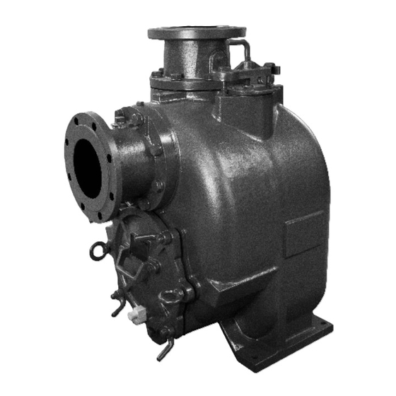
- Page 1 490 Series SXT 4”x4” Self-Priming Pumps Installation and Operating Manual *077-0241-000*...
-
Page 2: Table Of Contents
TABLE OF CONTENTS INTRODUCTION ........................- 3 - INSTALLATION SECTION B ......................- 6 - Pump Dimensions ......................- 6 - PREINSTALLATION INSPECTION ..................- 7 - POSITIONING PUMP ......................- 7 - Lifting ........................... - 7 - Mounting ........................- 7 - Clearance ........................ - Page 3 STOPPING ......................... - 17 - Cold Weather Preservation ..................- 17 - BEARING TEMPERATURE CHECK ..................- 18 - TROUBLESHOOTING SECTION D ..................... - 18 - PREVENTIVE MAINTENANCE .................... - 20 - PERFORMANCE CURVE ..................... - 22 - ILLUSTRATION ........................- 23 - PARTS LIST ........................
-
Page 4: Introduction
INTRODUCTION Thank You for purchasing an American-Marsh Pump. Read this manual carefully to learn how to safely install and operate your pump. Failure to do so could result in personal injury or damage to the pump. Because pump installations are seldom identical, this manual cannot possibly provide detailed instructions and precautions for every aspect of each specific application. - Page 5 HAZARD AND INSTRUCTION DEFINITIONS The following are used to alert maintenance personnel to procedures which require special attention, to those which could damage equipment, and to those which could be dangerous to personnel: DANGER: Immediate hazards which WILL result in severe personal injury or death. These instructions describe the procedure required and the injury which will result from failure to follow the procedure.
- Page 6 SAFETY SECTION A This information applies to the 490 Series SXT 4”x4” pumps. AMP has no control over or particular knowledge of the power source which will be used. Refer to the manual accompanying the power source before attempting to begin operation. This manual will alert personnel to known procedures which require special attention, to those which could damage equipment, and to those which could be dangerous to personnel.
-
Page 7: Installation Section B
INSTALLATION SECTION B Review all SAFETY information in Section A. Since pump installations are seldom identical, this section offers only general recommendations and practices required to inspect, position, and arrange the pump and piping. Most of the information pertains to a standard static lift application where the pump is positioned above the free level of liquid to be pumped. -
Page 8: Preinstallation Inspection
PREINSTALLATION INSPECTION The pump assembly was inspected and tested before shipment from the factory. Before installation, inspect the pump for damage which may have occurred during shipment. Check as follows: Inspect the pump for cracks, dents, damaged threads, and other obvious damage. b. -
Page 9: Suction And Discharge Piping
permit removal of the cover and easy access to the pump interior. A minimum clearance of 10 inches (254 mm) must be maintained to permit removal of the cover. SUCTION AND DISCHARGE PIPING Pump performance is adversely affected by increased suction lift, discharge elevation, and friction losses. -
Page 10: Sealing
If a strainer is not furnished with the pump, but is installed by the pump user, make certain that the total area of the openings in the strainer is at least three or four times the cross section of the suction line, and that the openings will not permit passage of solids larger than the solids handling capability of the pump. -
Page 11: Discharge Lines
Figure 2. Recommended Minimum Suction Line Submergence vs. Velocity DISCHARGE LINES Siphoning DO NOT terminate the discharge line at a level lower than that of the liquid being pumped unless a siphon breaker is used in the line. Otherwise, a siphoning action causing damage to the pump could result. -
Page 12: Bypass Lines
Bypass Lines Self‐priming pumps are not air compressors. During the priming cycle, air from the suction line must be vented to atmosphere on the discharge side. If the discharge line is open, this air will be vented through the discharge. However, if a check valve has been installed in the discharge line, the discharge side of the pump must be opened to atmospheric pressure through a bypass line installed between the pump discharge and the check valve. -
Page 13: Air Release Valve Installation
Some leakage (1 to 5 gallons [3.8 to 19 liters] per minute) will occur when the valve is fully closed. Be sure the bypass line is directed back to the wet well or tank to prevent hazardous spills * Consult the manual accompanying the Air Release Valve for additional information on valve installation and performance. -
Page 14: Alignment
ALIGNMENT The alignment of the pump and its power source is critical for trouble‐free mechanical operation. In either a flexible coupling or V‐belt driven system, the driver and pump must be mounted so that their shafts are aligned with and parallel to each other. It is imperative that alignment be checked after the pump and piping are installed, and before operation. -
Page 15: Drive Belts
every 90°. The coupling is in alignment when the hubs are the same distance apart at all points (see Figure 5). Check parallel adjustment by laying a straightedge across both coupling rims at the top, bottom, and side. When the straightedge rests evenly on both halves of the coupling, the coupling is in horizontal parallel alignment. -
Page 16: Operation Section C
foreign material which may cause slippage. OPERATION SECTION C Review all SAFETY information in Section A. Follow the instructions on all tags, labels and decals attached to the pump. This pump is designed to handle liquids containing large, entrained solids and slurries. DO NOT attempt to pump volatile, corrosive, or flammable liquids which may damage the pump or endanger personnel as a result of pump failure. -
Page 17: Operation
the pump from the motor before checking motor rotation. Operate the motor independently while observing the direction of the motor shaft, or cooling fan. If rotation is incorrect on a three‐phase motor, have a qualified electrician interchange any two of the three phase wires to change direction. -
Page 18: Strainer Check
prevent injury to personnel from hot liquid. As a safeguard against rupture or explosion due to heat, this pump is equipped with a pressure relief valve which will open if vapor pressure within the pump casing reaches a critical point. If overheating does occur, stop the pump immediately and allow it to cool before servicing it. -
Page 19: Bearing Temperature Check
remaining liquid that could freeze the pump rotating parts. If the pump will be idle for more than a few hours, or if it has been pumping liquids containing a large amount of solids, drain the pump, and flush it thoroughly with clean water. To prevent large solids from clogging the drain port and preventing the pump from completely draining, insert a rod or stiff wire in the drain port, and agitate the liquid during the draining process. - Page 20 TROUBLE POSSIBLE CAUSE PROBABLE REMEDY PUMP FAILS TO Not enough liquid in casing. Add liquid to casing. See PRIMING. PRIME Suction check valve contaminated or Clean or replace check valve. damaged. Air leak in suction line. Correct leak. Lining of suction hose collapsed. Replace suction hose.
-
Page 21: Preventive Maintenance
EXCESSIVE NOISE Cavitation in pump. Reduce suction lift and/or friction losses in suction line. Record vacuum and pressure gauge readings and consult local representative or factory. Pumping entrained air. Locate and eliminate source of air bubble. Pump or drive not securely mounted. Secure mounting hardware. - Page 22 Preventive Maintenance Schedule Service Interval* Item Daily Weekly Monthly Semi‐ Annually Annually General Condition (Temperature, Unusual Noises or Vibrations, Cracks, Leaks, Loose Hardware, Etc.) Pump Performance (Gauges, Speed, Flow) Bearing Lubrication Seal Lubrication (And Packing Adjustment, If So Equipped) V‐Belts (If So Equipped) Air Release Valve Plunger Rod (If So Equipped) Front Impeller Clearance (Wear Plate) Rear Impeller Clearance (Seal Plate)
-
Page 23: Performance Curve
PUMP MAINTENANCE AND REPAIR SECTION E MAINTENANCE AND REPAIR OF THE WEARING PARTS OF THE PUMP WILL MAINTAIN PEAK OPERATING PERFORMANCE. PERFORMANCE CURVE * STANDARD PERFORMANCE FOR PUMP MODEL SXT-4”X4” Based on 70°F (21° C) clear water at sea level with minimum suction lift. Since pump installations are seldom identical, your performance may be different due to such factors as viscosity, specific gravity, elevation, temperature, and impeller trim. -
Page 24: Illustration
ILLUSTRATION Figure 1. Pump Model SXT-4”X4”... -
Page 25: Parts List
PARTS LIST Pump Model SXT-4”X4” Contact AMP to verify part numbers. PART NAME PART NAME PART NAME Cap screw Pipe Plug O-Ring Lock Washer Lifting Bolt / Eye Bolt Seal Plate Pipe Plug Pump Casing Seal Plate Gasket Suction Flange Cap screw Inboard Oil Seal Check Valve Pin... -
Page 26: Pump And Seal Disassembly And Reassembly
PUMP AND SEAL DISASSEMBLY AND REASSEMBLY Review all SAFETY information in Section A. Follow the instructions on all tags, label and decals attached to the pump. This pump requires little service due to its rugged, minimum‐maintenance design. However, if it becomes necessary to inspect or replace the wearing parts, follow these instructions which are keyed to the illustration (see Figure 1) and the accompanying parts lists. -
Page 27: Suction Check Valve Removal
The wear plate (42) is easily accessible and may be serviced by removing the back cover (36). Before attempting to service the pump, remove the pump casing drain plug (43) and drain the pump. Clean and reinstall the drain plug. Remove the hand nuts (34) and studs (35) and pry the back cover and assembled wear plate from the pump casing (28). -
Page 28: Impeller Removal
Figure 2. Loosening Impeller Figure 3. Rotating Assembly Tool (Figure 1) Remove the hardware (63 and 64) securing the rotating assembly to the pump casing. Separate the rotating assembly by pulling straight away from the pump casing. Tie and tag the rotating assembly adjusting flat washers (60) for ease of reassembly. -
Page 29: Seal Removal
Seal Removal (Figure 1) Slide the integral shaft sleeve and rotating portion of the seal off the shaft as a unit. Use a pair of stiff wires with hooked ends to remove the stationary element and seat. An alternate method of removing the stationary seal components is to remove the hardware (58 and 59) and separate the seal plate (52) and gasket (53) from the bearing housing (57). -
Page 30: Shaft And Bearing Reassembly And Installation
Bearings must be kept free of all dirt and foreign material. Failure to do so will greatly shorten bearing life. DO NOT spin dry bearings. This may scratch the balls or races and cause premature bearing failure. Rotate the bearings by hand to check for roughness or binding and inspect the bearing balls. If rotation is rough or the bearing balls are discolored, replace the bearings. -
Page 31: Seal Installation
After the bearings have been installed and allowed to cool, check to ensure that they have not moved away from the shaft shoulders in shrinking. If movement has occurred, use a suitably sized sleeve and a press to reposition the bearings against the shaft shoulders. If heating the bearings is not practical, use a suitably sized sleeve and an arbor (or hydraulic) press to install the bearings on the shaft. - Page 32 Figure 4. Cartridge Seal Assembly This seal is not designed for operation at temperatures above 160°F (71°C). DO NOT use at higher operating temperatures If the seal plate (52) was removed, install the seal plate gasket (53). Position the seal plate over the shaft and secure it to the bearing housing with the hardware (57 and 58).
- Page 33 Figure 5. Seal Partially Installed Figure 6. Seal Fully Installed Continue to screw the impeller onto the shaft. This will press the stationary seat into the seal plate bore. NOTE A firm resistance will be felt as the impeller presses the stationary seat into the seal plate bore. As the stationary seat becomes fully seated, the seal spring compresses, and the shaft sleeve will break the nylon shear ring.
-
Page 34: Impeller Installation And Adjustment
the shaft sleeve. Slide the rotating portion of the seal (consisting of the integral shaft sleeve, spring centering washer, spring, bellows and retainer, and rotating element) onto the shaft until the seal faces contact. Proceed with Impeller Installation and Adjustment. Impeller Installation and Adjustment (Figure 1) Inspect the impeller and replace it if cracked or badly worn. -
Page 35: Suction Check Valve Installation
Suction Check Valve Installation (Figure 1) Inspect the check valve assembly (8~13), replace it if badly worn. NOTE The check valve assembly must be replaced as a complete unit. Individual parts are not sold separately. Reach through the back cover opening with the check valve and position the check valve adaptor in the mounting slot in the suction flange (4). - Page 36 Figure 7. Installing and Adjusting Back Cover Screw the four adjusting studs (35) into the tapped holes in the back cover plate until they are just flush with the machined surface on the back side of the cover plate. Align the back cover plate over the two eye bolts (32) and slide it into the pump casing. Use two hand nuts (34) on diagonally opposing studs to press the back cover into the pump casing until the wear plate just touches the impeller when the shaft is turned by hand.
-
Page 37: Pressure Relief Valve Maintenance
rotating assembly adjusting flat washers (60). Allow an installed pump to completely cool before draining liquid from the pump casing. Remove the back cover. Remove the rotating assembly adjusting shims, then reinstall the hardware securing the rotating assembly to the pump casing. Perform the back cover adjustment procedure described above to obtain the proper face clearance. -
Page 38: Bearings
The white reflector in the sight gauge must be positioned horizontally to provide proper drainage. Bearings (Figure 1) The bearing housing was fully lubricated when shipped from the factory. Check the oil level regularly through the sight gauge (65, the lower one) and maintain it at the middle of the gauge. When lubrication is required, add SAE No. -
Page 39: Warranty
WARRANTY American-Marsh Pumps guarantees that only high-quality materials are used in the construction of our pumps and that machining and assembly are carried out to high standards. The pumps are guaranteed against defective materials and/or faulty craftsmanship for a period of one (1) year from the date of shipment unless specifically stated otherwise.
Need help?
Do you have a question about the AMERICAN-MARSH PUMPS SXT 4x4 490 Series and is the answer not in the manual?
Questions and answers