Wisi MIDI Series Operating Instructions Manual
Hide thumbs
Also See for MIDI Series:
- Operating instructions manual (20 pages) ,
- Operating instructions manual (16 pages)

Related Manuals for Wisi MIDI Series


Summary of Contents for Wisi MIDI Series
- Page 1 Operating instructions VX 12 K 3626, ...4432 WISI MIDI LINE Connecting past, present and future. wisigroup.com...
- Page 2 Stay up to date For more information on your device, visit our support-website: www.wisiconnect.tv After logging in/registering, you will have access to a variety of interesting infor- mation and features, such as release notes or installation examples.
-
Page 3: Table Of Contents
Table of Contents Table of Contents Important information 1 About this document ......... . .4 1.1 Structure of warnings . -
Page 4: Important Information
1 About this document These operating instructions are part of the device. If the warnings, notes and instructions in this document are not followed, WISI does not assume any warranty or liability for safe operation and function of this device. -
Page 5: Safety Instructions
The device is used exclusively for the installation of HFC networks up to 1218 MHz. 2.3 Improper use Any other use will result in the loss of warranty or guarantee. WISI is not liable for any damages resulting from this. The user bears the sole risk. 2.4 Specialist personnel 2.4.1 Assembly and repair •... -
Page 6: Esd Protection
Important information • When working on the device of any kind, the device must be de-energized. • The device may only be installed and put into operation in a dry room. • Do not expose the device to splash water or other liquids. Do not place liquids on the device. -
Page 7: Overview
Overview Overview 4 VX 12 K 3626, VX 12 K 4432 Cascadable Amplifier, 1 Output • Compact 1.2 GHz cascadable amplifier with one active output • Aluminium die-casting housing • Integrated diplex filters • Configuration of attentuation, equalization and slope via PADs and jumpers •... -
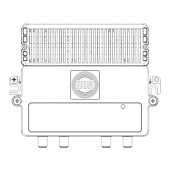
Page 8: Dimensions
Overview 4.1 Dimensions 8 | EN... -
Page 9: Connectors And Adjustment Elements
Overview 4.2 Connectors and adjustment elements VX12 K 4432 0 / 7 dB EQ /dB Grün 258-1218 Orange -6dB M10 - Transponder 0 dB 6 dB VX12 K 4432 INPUT DS TP - 20dB TP - 20dB OUTPUT DS Downstream-Input Downstream RF test point Upstream RF test point Downstream-Output... -
Page 10: Block Diagram
Overview 4.3 Block diagram The block diagram of VX 12 E 4432 serves as an example. The other variants differ in some adjustable values. For detailed information see technical data. 10 | EN... -
Page 11: Technical Data
Overview 4.4 Technical data The latest technical data can be found on the Internet at www.katalog.wisi.de. General ...4432 ...3626 Compliance VF TS4002 RF connector 75 Ω Impedance RF test point at the input -20 (±1 dB, 10...204 MHz) (bidirectional) -20 (±2.5 dB, 258...1218 MHz) RF test point at the output -20 (±1 dB) - Page 12 Overview Downstream ...4432 ...3626 Frequency range 258...1218 MHz Gain 44/36 dB switchable 36 dB Frequency response ± 0.8 dB ≥16.5 dB (-1.5 dB/Oct.) In/output return loss ≤ 6 dB ≤5.5 dB Noise figure ≤109 dBµV ≤105 dBµV Output level with 7 dB slope ≤106 dBµV ≤102 dBµV Operational level...
-
Page 13: Installation
Installation Installation 5 Commissioning DANGER Injuries due to electric shock Disconnect the mains plug before opening. Never touch live parts. The device contains components that are sensitive to electrostatic discharges. Always take the usual protective measures when handling the device. 5.1 Open the cover Loosen the cover screws and open the cover. - Page 14 Installation 5.2.3 Input equalizer (X3) The equalization can be adjusted via a PAD in 1 dB steps. Set equalizer (PAD) according to the following table. Equalizer PAD Attenuator 258...1218 MHz (dB) (dB) 5.2.4 Amplifier (X4) Valid only for ...4432: The amplifier in downstream can be set via a jumper. 44 dB 36 dB 5.2.5 Interstage Slope (X5)
-
Page 15: Configure Upstream
Installation 5.3 Configure upstream 5.3.1 Input attenuator (X10) The attenuation can be adjusted via a PAD in 1 dB steps. Set the attenuation (PAD) according to the level plan. 5.3.2 Interstage attenuator (X11) Valid only for ...4432: The interstage attenuator can be set via a jumper. Set the interstage attenuator (jumper) according to the level plan 0 dB 6 dB... -
Page 16: Establish Potential Equalisation
Installation 5.5 Establish potential equalisation Connect the unit to a potential equalisation system in accordance with the locally applicable electrical standards. For this purpose, one of the two places marked with must be used. 5.6 Close the cover and connect the device to the mains Close the cover and tighten the cover screws. - Page 20 WISI Communications GmbH & Co. KG Wilhelm-Sihn-Str. 5-7 75223 Niefern-Öschelbronn, Germany Fon: +49 7233 66 0 wisigroup.com info@wisigroup.com...
Need help?
Do you have a question about the MIDI Series and is the answer not in the manual?
Questions and answers