
Related Manuals for Phenix Technologies MRM-10


Summary of Contents for Phenix Technologies MRM-10
- Page 1 User’s Manual MRM-10 Digital micro-ohmmeter Phenix Technologies, Inc 75 Speicher Drive Accident, MD 21520 GF-2016 © Phenix Technologies, Inc. Rev 11/14/2016 nab MRM-10...
- Page 2 SECTION 1: DANGER / GENERAL SAFETY PRECAUTIONS WARNING !! Complete Grounding of this unit is necessary for the safe operation of this equipment. Disconnect inputs before ungrounding this equipment. MRM-10...
- Page 3 DO NOT operate damaged equipment. Remove power and do not use the equipment until safe operation can be verified by service-trained personnel. Phenix Technologies, Inc. assumes no liability for unsafe or improper use of test equipment. MRM-10...
- Page 4 Equipment complies with current EU Directives. The rubbish bin with a line through it means that in the European Union, the product must undergo selective disposal for the recycling of electric and electronic material, in compliance with Directive WEEE 2002/96/EC. MRM-10...
-
Page 5: Table Of Contents
3.2. BATTERY CHARGER ............4. MEASUREMENT ................5. MESSAGES .................. 6. SOME NOTES ABOUT ACCURACY ........... 7. RS232 OUTPUT ................8. CLEANING ................... 9. REPLACEMENT FUSE ..............10. TECHNICAL SPECIFICATIONS ..........11. CUSTOMER COMMENTS / SUGGESTIONS ......Error! Bookmark not defined. MRM-10... -
Page 6: Description
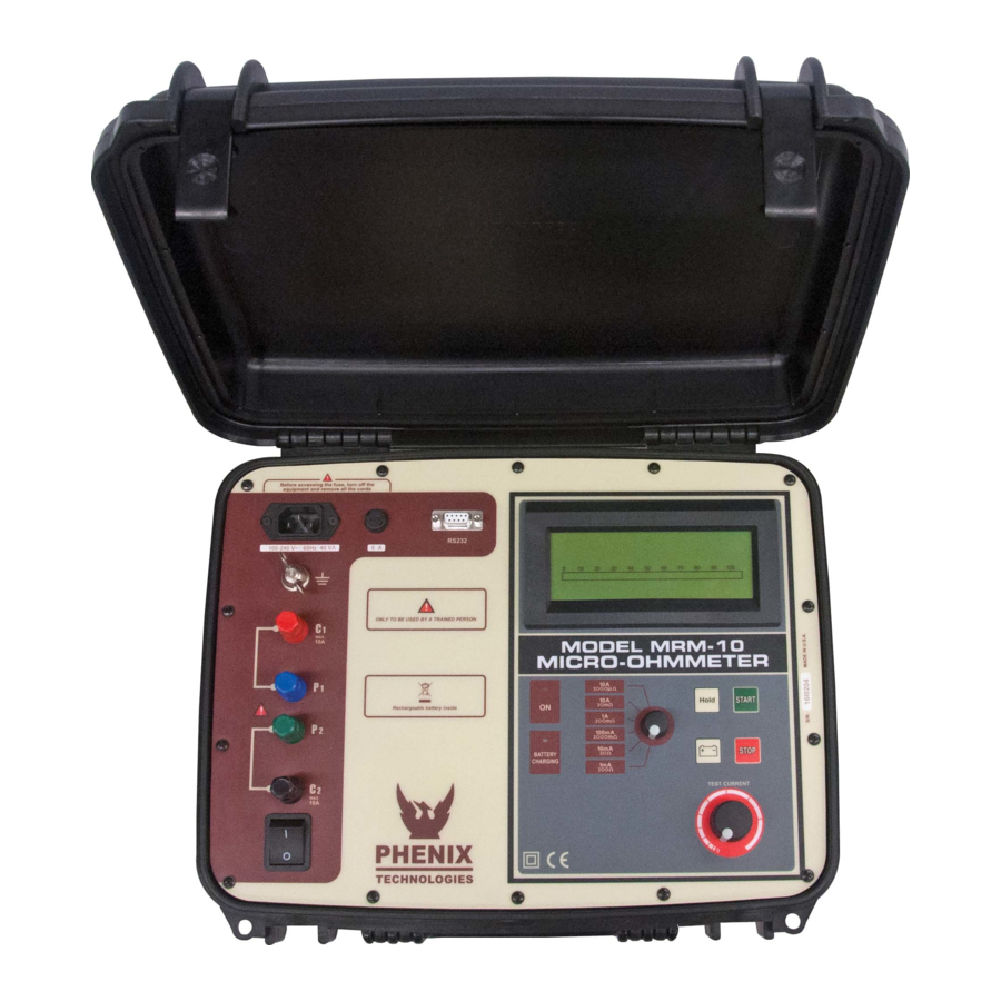
1. Description The MRM-10 micro-ohmmeter is a portable, microprocessor controlled instrument, used to accurately measure very low contact resistances of breakers and switches, bus bars, transformers and engine windings, etc, with test currents from 1mA to 10A. Kelvin architecture (four-terminal method). -
Page 7: Control Panel
17. Hold Key (retains last measurement in the display) 6. Potential Terminals (P+ P-) 7. Current Terminal (C-) 8. ON / OFF Switch 9. Displays both measured resistance value & messages 10. ON Indicator LED 11. Battery Charge Iindicator 12. Range & Test Current Selector MRM-10... -
Page 8: Power Supply
Connect the equipment to the mains supply. The battery charge indicator will display a red light up to completing the charge. At that point, it will change to a green light, and remain so until the equipment is disconnected from the mains supply MRM-10... -
Page 9: Measurement
10. Press the Stop key in order to finish the measurement. Do not turn Off the equipment without pressing the Stop key. 11. Finally, after finishing measurements, turn the equipment Off using the On/Off switch. CAUTION: Do not connect or disconnect the test leads during the measurement. MRM-10... -
Page 10: Messages
It indicates that the measured resistance is higher than the maximum value readable in the selected range. Indicates that the value is the one retained in the memory when pressing the hold key. It shows that the battery is discharged. Recharge the battery. MRM-10... -
Page 11: Some Notes About Accuracy
80% of the nominal value. If it were necessary, it is possible to use a lower current, but by doing this the accuracy will be affected. MRM-10 has an auto-compensation system that automatically eliminates the error produced by internal offset. Thus, it is not necessary to carry out measurements by reversing the polarity in order to compute the average value. -
Page 12: Rs232 Output
8 bits - no parity - 1 stop bit (8,n,1) Note: In order to assure the compatibility with most printers available in the market, the resistance units are shown with the following symbols: uR = micro-ohm mR = milli-ohm R = ohm MRM-10... -
Page 13: Cleaning
The panel, terminals and connectors of the equipment must stay dry and clean. Cleaning should be made using a wet cloth in water and a soft detergent or isopropyl alcohol (be sure that the products to be used for cleaning do not affect plastic goods). MRM-10... -
Page 14: Replacement Fuse
9. Replacement Fuse To check the instrument fuse, remove it with a screw driver. If the fuse is ruptured, replace it by another with the following specifications: Fuse Schurter, model SPT 5x20 (Time-lag) 5A/250V. High breaking capacity. MRM-10... -
Page 15: Technical Specifications
: 378 x 308 x 175 mm (15 x 12 x 7 in.) Accessories : 2 Combined current and potential leads (1.8 m, 70 in.). 1 Ground cable. 1 Communication cable (RS-232). 1 Power cord. 1 User guide. 1 Carrying bag. Subject to technical change without notice. MRM-10... -
Page 16: Customer Comments / Suggestions
SECTION 11: CUSTOMER COMMENTS / SUGGESTIONS Phenix Technologies made significant efforts to ensure that the materials in this Operator’s Manual are correct. If there are concerns or comments as you have used this information, Phenix Technologies appreciates any feedback. Unit Serial Number:...
Need help?
Do you have a question about the MRM-10 and is the answer not in the manual?
Questions and answers