
Subscribe to Our Youtube Channel
Related Manuals for Gravely Pro-Turn Z52


Summary of Contents for Gravely Pro-Turn Z52
- Page 1 ™ Pro-Turn Z Operator’s Manual Manuel de I’utilisateur Models 991188 – Pro-Turn Z52 (SN 000101 +) 991190 – Pro-Turn Z60 (SN 000101 +) ENGLISH • 05179300A 10/18 FRANÇAIS Printed in USA...
-
Page 2: Table Of Contents
TABLE OF CONTENTS WELCOME ..... . 1 Service Position ....19 Maintenance Schedule . -
Page 3: Welcome
WELCOME Congratulations on your purchase and welcome to the Gravely family! Every machine in the Gravely lineup is designed for long-lasting and unsurpassed performance. We are confident your machine will be part of your family for many years to come. -
Page 4: Safety
If you have purchased this 2. Warning product from a Gravely dealer, the dealer can provide you with training. WARNING: Indicates a Familiarize yourself and any other operators POTENTIALLY HAZARDOUS... -
Page 5: Safety Decals
4. Notice SAFETY DECALS NOTICE: Indicates information or procedures The safety decals on your unit are visual that are considered important but not hazard reminders of the important safety information related. If not followed, property damage in this manual. All messages on your unit could result. - Page 6 Safety Decal Descriptions 1.3 Tipping Hazard 1. DANGER! Avoid tipping hazard. DANGER! DO NOT operate on slopes over 15°. Read Operator’s Manual. 1.1 Amputation Hazard DO NOT operate on slopes over 15°. To avoid amputation hazard, DO NOT put hands near 1.4 Service Hazard rotating blades.
- Page 7 3. DANGER! Look behind when operating Discharge Hazard – NEVER the unit in reverse. direct discharge toward people, pets or property. Thrown objects can cause 1.6 Loss of Traction Hazard injury or damage. If loss of traction is Amputation Hazard – experienced do the NEVER stick hands or feet following:...
-
Page 8: Safety Rules
5. HOT SURFACES! 8. DANGER! DO NOT touch parts which Keep hands and feet away are hot from operation. from all rotating or moving ALWAYS allow parts to cool. parts. 6. ROTATING PARTS! 9. WARNING! Overfilling may cause severe damage to AVOID INJURY. - Page 9 Understand: Use extreme care when approaching blind corners, shrubs, trees, or other objects that • How to operate all controls may block your view of a child. • The functions of all controls Keep children out of the mowing area and in •...
- Page 10 Keep safety devices or guards in place and Operation functioning properly. NEVER modify or Be sure the area is clear of bystanders remove safety devices. before operating. Stop machine if anyone DO NOT mow in reverse unless absolutely enters the area. necessary.
- Page 11 DO NOT operate on slopes of more than Extinguish all cigarettes, cigars, pipes, and 15°. other sources of ignition. Mow up and down slopes, not across. Use only an approved gasoline container. Watch for holes, ruts, bumps, rocks, or other NEVER store the machine or fuel container hidden objects.
- Page 12 DO NOT wear a seat belt while operating Accessories the unit with the center bar in the lowered Use only Ariens Company-recommended position. attachments or accessories that are DO NOT weld, cut, drill or modify ROPS in designed for your unit and that are any manner unless instructed by the appropriate to your use and can be used manufacturer.
- Page 13 Transporting Unit Use extra care when loading or unloading the machine into a trailer. Secure unit chassis to transport vehicle. NEVER secure from rods or linkages that could be damaged. DO NOT transport machine while engine is running. ALWAYS turn off power to attachment and shut off fuel when transporting unit.
-
Page 14: Assembly
ASSEMBLY WARNING: AVOID INJURY. Read and understand the Safety section before proceeding. 1. Remove wrap and packaging materials from unit. 2. Remove unit from shipping container. See Move Unit Manually on page 18. 3. Remove hardware from negative (-) battery cable, but DO NOT discard. 4. -
Page 15: Controls And Features
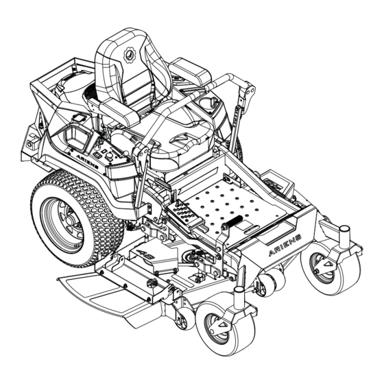
CONTROLS AND FEATURES Figure 6 1. Fuel Tank and Cap 14. Deck Lift Pedal 2. Fuel Level Window 15. Rollover Protection Structure (ROPS) 3. Oil Filter 16. Seat Adjustment Lever 4. Oil Drain 17. Seat Latch 5. Engine Oil Dipstick 18. -
Page 16: Ignition Key
THROTTLE CONTROL LEVER WARNING: AVOID INJURY. See Figure 9. Read and understand the Controls engine speed. Safety section before proceeding. See Figure 6 for all controls and features locations. Fast IGNITION KEY See Figure 7. Controls power to the engine. The key cannot be removed when in run position. -
Page 17: Transport Lock Release Lever
TRANSPORT LOCK RELEASE PARKING BRAKE LEVER LEVER See Figure 12. See Figure 11. Controls the parking brake. The engine will not start with brake in the off position. Releases deck from transport lock position. Brake Engaged (On) Brake Released (Off) Figure 11 DECK LIFT PEDAL Raises mower deck to change height-of-cut... -
Page 18: Operation
4. Check function of the Safety Interlock System by performing the tests in Check Safety Interlock System on page 20. Contact your Gravely dealer for repair if any of the tests fail. 5. Set cutting height. See Figure 13. a. Push mower lift pedal forward until transport lock engages. -
Page 19: Start The Engine
Lower Center Bar 2. Move steering levers to neutral position. 3. Engage parking brake. See Figure 15. 4. If engine is cold, pull choke knob up to on position. If engine is warm or hot, turn WARNING: AVOID INJURY. choke off. Lower the center bar only when needed to drive under 5. -
Page 20: Move Unit Manually
IMPORTANT: There is one transaxle bypass Direction Lever Position lever on each side of unit. Ensure that both of Travel levers are fully in front or rear position. Left Turn Push right lever 1. Stop engine, remove key and wait for farther forward moving parts to stop and for hot parts to than the left lever. -
Page 21: Transport Unit
The Maintenance Schedule on page 19 Service Performed shows the recommended service schedule. Check Safety Interlock • Your Gravely dealer can provide service and System adjustments to keep your unit operating at Check Hydraulic System • peak efficiency. Contact an authorized engine Check Parking Brake •... -
Page 22: Service Parts
Check function of the Safety Interlock System cannot be reset. by performing the tests below. Contact your Maintenance Models Gravely dealer for repair if any of the tests fail. See Figure 19. When the key is in the on position, the Timer... -
Page 23: Check Parking Brake
CHECK FASTENERS Test Steering PTO Parking Result Levers Brake Check for loose or missing hardware. Starting Interlock LUBRICATE UNIT Forward, On or Engine 1. Apply oil to all pivot points and pin Neutral, shuts off. connections. Reverse Lubricate Seat Forward, Engine Neutral, shuts off. - Page 24 DO NOT sharpen to this pattern. Sharpen to this pattern. Figure 21 Sharpen Blades DISCARD if more than CAUTION: DO NOT sharpen 1.3 cm (1/2") blades while attached to unit. 1. Cutting Edge 2. Square Corner 1. Remove blades. Discard blades if: 3.
-
Page 25: Battery Service
5. Charge battery following battery manufacturer’s instructions. 6. Reinstall battery. See Install Battery on page 23. Jump Starting Gravely does not recommend jump starting your unit. Jump-starting can damage engine and system components. Refer to engine 1. T Bracket manual for details. - Page 26 Fill expansion tanks with 15W-50 N•m (65 lb-in). DO NOT overtighten. synthetic motor oil (Gravely p/n 00057100) or equivalent) until oil 10. Add 15W-50 synthetic motor oil (Gravely reaches the cold fill indicator mark. p/n 00057100) or equivalent) until oil See Figure 24.
-
Page 27: Service & Adjustments
2. Release parking brake. ADJUST STEERING LEVERS 3. Support unit so drive wheels are off the Adjust Height ground. The steering lever height may be adjusted for 4. Bypass transaxles. See Move Unit operator comfort. Manually on page 18. See Figure 27. 5. -
Page 28: Adjust Unit To Drive Straight
4. Tighten hardware. ADJUST UNIT TO DRIVE STRAIGHT NOTICE: Reverse travel can only be adjusted by your Gravely dealer. Adjust Tire Pressure 1. Place unit in service position. See Service Position on page 19. 2. Check tire pressures. If needed, adjust to recommended pressures. -
Page 29: Adjust Transaxles
Adjust Neutral Position If wheel hub has excessive rotation after checking for excessive creep, adjust neutral position. 1. Loosen the return-to-neutral screw on the transaxle. See Figure 31. Figure 30 3. Align steering levers. See Adjust Steering Levers on page 25. Figure 31 ADJUST TRANSAXLES 2. -
Page 30: Electrical Service
6. Check wheel hubs for rotation. REPLACE MOWER BELTS • If there is only slight rotation, stop CAUTION: Damage or worn engine, reinstall wheels, return unit to belts may result in injury and / or operating position and advance to damage to the unit. - Page 31 Install Mower Drive Belt See Figure 37. 1. Install mower drive belt around bottom groove of split pulley at deck center and around bottom groove of right spindle pulley. 2. Reinstall idler spring hook around anchor bolt to apply tension to belt. 1.
-
Page 32: Replace Transaxle Drive Belt
3. Under unit, slowly remove spring hook from anchor bolt to release transaxle idler tension. See Figure 40. Figure 38 IMPORTANT: Make sure belt has tension and is aligned in all pulleys. See Figure 39. 1. Spring 2. Anchor Bolt 3. -
Page 33: Reverse Clutch Brake Plates
b. From left transaxle sheave. c. From clutch sheave. Install Transaxle Drive Belt See Figure 42. 1. Install transaxle drive belt to drive system in the following order: a. Around clutch sheave. b. Around left transaxle sheave. c. Around right transaxle sheave. 2. -
Page 34: Adjust Anti-Scalp Wheels
• To increase lever response, loosen the upper jam nut and tighten the lower jam nut until both jam nuts are tight against cable bracket. • To decrease lever sensitivity, loosen the lower jam nut and tighten the upper jam nut until both jam nuts are tight against cable bracket. -
Page 35: Level And Pitch Mower Deck
1. Lift-Assist Spring 2. Spring Peg Figure 50 Figure 48 8. Remove deck from under unit. 6. Remove hardware retaining drag links to frame. See Figure 49. Install Deck 1. Position deck under unit. See Figure 51. 2. Reinstall drag links to frame with original hardware. - Page 36 Check Blade Level and Pitch necessary. d. Tighten jam nuts against deck- 1. Raise deck to 3 1/2" (8.9 cm) cutting leveling links. height. 2. Raise the low side of deck: 2. Stop engine, remove key and wait for moving parts to stop and for hot parts to a.
- Page 37 e. Tighten jam nuts against deck- leveling links. 2. Decrease forward pitch: a. Loosen jam nuts against all deck- leveling links. b. Turn front adjustment bolts clockwise to raise deck front. c. Turn rear adjustment bolts counterclockwise to lower deck rear. d.
-
Page 38: Troubleshooting
Connect spark plug wire(s) or replace spark plug(s) are faulty. spark plug(s). Refer to engine manual. Electrical system is faulty. Contact your Gravely dealer. Engine is faulty. Contact your Gravely dealer. Choke control knob is in on Move knob to off position. - Page 39 TROUBLESHOOTING Problem Probable Cause Correction Mower blades not level or mower Level and adjust pitch of mower deck. deck pitch is incorrect. See Level and Pitch Mower Deck on page 33. Mower blades are dull or faulty. Sharpen or replace mower blades. See Sharpen Blades on page 22.
-
Page 40: Storage
2. Tighten all hardware to correct ACCESSORIES specifications. 3. Inspect unit for visible signs of wear or See your Gravely dealer for a complete list of damage. Repair as needed. compatible accessories and attachments for 4. Prepare fuel system for storage. -
Page 41: Specifications
3600 ± 100 Oil Capacity Refer to engine manual. Liquid or Air Cooled Transmission Type Hydrostatic Drive 15W-50 synthetic motor oil (Gravely p/n 00057100) or equivalent Hydraulic Oil Filter Drive Forward Maximum – km/h (mph) 12.9 (8) Reverse Maximum – km/h (mph) 6.4 (4) -
Page 42: Warranty
90 days after the date of purchase. An authorized Gravely dealer will repair any defect in material or workmanship, and repair or replace any defective part, subject to the conditions, limitations and exclusions set forth herein. Such repair or replacement will be free of charge (labor and parts) to the original purchaser;... - Page 43 Exclusions – Items Not Covered by This Warranty • Parts that are not genuine Gravely service parts are not covered by this warranty and may void the war- ranty if the parts result in premature wear or damage to the product.
- Page 44 • Renting or leasing the vehicle. • Using the vehicle to tow or carry loads in excess of the limits specified in the operator’s manual. • Modifying the vehicle with parts and accessories that are not genuine or authorized Gravely parts or accessories.
- Page 45 Disclaimer Ariens Company may from time to time change the design of its products. Nothing contained in this warranty shall be construed as obligating the Ariens Company to incorporate such design changes into previously manufactured products, nor shall such changes be construed as an admission that previous designs were defective.
- Page 46 655 West Ryan Street Brillion, WI 54110 www.gravely.com...
Need help?
Do you have a question about the Pro-Turn Z52 and is the answer not in the manual?
Questions and answers
the back rest is in such a reclining position it gives no support. I need to raise the back rest upright.