Pit Boss PB2BGD2 - 2-Burner Ultimate Lift-Off Plancha Manual
- Owner's manual (21 pages) ,
- Assembly manual (8 pages) ,
- Assembly manual (26 pages)
Advertisement
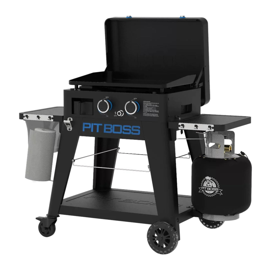
PARTS & SPECS

READ CAREFULLY, RETAIN FOR FUTURE REFERENCE. MANUAL MUST BE READ BEFORE OPERATING!

PLEASE READ THE ENTIRE MANUAL BEFORE INSTALLATION AND USE OF THIS GAS APPLIANCE. FAILURE TO FOLLOW THESE INSTRUCTIONS COULD RESULT IN PROPERTY DAMAGE, BODILY INJURY OR EVEN DEATH. CONTACT LOCAL BUILDING OR FIRE OFFICIALS ABOUT RESTRICTIONS AND INSTALLATION INSPECTION REQUIREMENTS IN YOUR AREA.

| Part# | Description |
| 1 | Firebox (x1) |
| 2 | Hot Plate (x1) |
| 3 | Hot Plate Leg Screws (x4) |
| 4 | Grease Cup (x1) |
| 5 | Lid Support (x1) |
| 6 | Lid Handle Bezel (x2) |
| 7 | Lid Handle (x1) |
| 8 | Cart Front Panel (x1) |
| 9 | Cart Back Panel (x1) |
| 10 | Cart Side Panel - Left (x1) |
| 11 | Cart Side Panel - Right (x1) |
| 12 | Side Shelf - Left (x1) |
| 13 | Side Shelf - Right (x1) |
| 14 | Paper Towel Hook (x1) |
| 15 | Side Shelf Bracket - Left (x2) |
| 16 | Side Shelf Bracket - Right (x2) |
| 17 | Support Leg for Caster - Front (x1) |
| 18 | Support Leg for Caster - Back (x1) |
| 19 | Support Leg for Wheel - Front (x1) |
| 20 | Support Leg for Wheel - Back (x1) |
| 21 | Bottle Opener (x1) |
| 22 | Locking Caster (x2) |
| 23 | Wheel (x2) |
| 24 | Bottom Shelf (x1) |
| A | Screw (x37) |
| B | Washer (x16) |
| C | Locking Washer (x16) |
| D | Screw (x4) |
| E | Wheel Cotter Pin (x2) |
| F | Wheel Washer (x2) |
| G | Wheel Axle Pin (x2) |
| H | Battery (x1) |
NOTE: Due to ongoing product development, parts are subject to change without notice. Contact Customer Care if parts are missing when assembling the unit.
| MODEL | ASSEMBLED (WxDxH) | WEIGHT | COOKING AREA | HEAT INPUT | |
| PB | PB2BGD2 | 1,273 X 728 X 940 MM / 50.1 X 28.6 X 37.0 IN | 46.4 KG / 102.3 LB | 2,720 CM² / 421.6 IN² | 7.63 KW |
ASSEMBLY PREPARATION
Parts are located throughout the shipping carton, including underneath the griddle. Inspect the unit, parts, and hardware blister pack after removing from the protective shipping carton. Discard all packaging materials from inside and outside of the griddle before assembly, then review and inspect all parts by referencing the parts list. If any part is missing or damaged, do not attempt to assemble. Shipping damage is not covered under warranty. Contact your dealer or Pit Boss® Grills Customer Care. www.pitboss-grills.com
To ease installation, using two people is helpful (but not necessary) when assembling this unit.
Tools required for assembly: screwdriver and wrench. Tools not included.

ASSEMBLY INSTRUCTIONS
It is advised to read each step entirely before starting assembly on instructions. Do not tighten screws completely until all screws for that step have been installed. Hardware combination involving a locking washer and washer should be installed with the locking washer closest to the head of the screw.
- CONNECTING THE WHEELS TO THE LEGS
Parts Required:
1 x Support Leg for Caster / Front (#17)
1 x Support Leg for Caster / Back (#18)
1 x Support Leg for Wheel / Front (#19)
1 x Support Leg for Wheel / Back (#20)
2 x Locking Caster (#22)
2 x Wheel (#23)
2 x Wheel Cotter Pin (#E) 2 x Wheel Washer (#F)
2 x Wheel Axle Pin (#G)
Installation:- Attach the Wheel to the Support Leg for Wheel by inserting the Wheel Axle Pin through the Wheel, Support Leg hole, Wheel Washer, then secure using the Wheel Cotter Pin. Repeat installation for the other Support Leg with Wheel. Note illustration 1A.
![]()
- Install a Locking Caster Wheel to the bottom of a Support Leg by hand-tightening into the hole. The Locking Caster Wheel is inserted completely when it cannot rotate any further into the Support Leg.
Repeat installation for second Support Leg. Note illustration 1B.
![]()
- Attach the Wheel to the Support Leg for Wheel by inserting the Wheel Axle Pin through the Wheel, Support Leg hole, Wheel Washer, then secure using the Wheel Cotter Pin. Repeat installation for the other Support Leg with Wheel. Note illustration 1A.
- ASSEMBLING THE CART BASE
Parts Required:
1 x Bottom Shelf (#24)
4 x Screw (#A)
4 x Washer (#B)
4 x Locking Washer (#C)
Installation:
![]()
- Place a piece of cardboard on the floor to prevent scratching the unit and parts during assembly.
NOTE: Ensure the flat surface of the Bottom Shelf is facing up. - Attach the Bottom Shelf to one Support Leg with Wheel by carefully aligning it into the corner, then secure using one washer, locking washer, and screw. Repeat installation for the other three Support Legs to the remaining three corners of the Bottom Shelf. See illustration for proper arrangement of the Support Legs.
- Place a piece of cardboard on the floor to prevent scratching the unit and parts during assembly.
- MOUNTING THE CART PANELS
Parts Required:
1 x Cart Front Panel (#8)
1 x Cart Back Panel (#9)
1 x Cart Side Panel - Left (#10)
1 x Cart Side Panel - Right (#11)
16 x Screw (#A)
Installation:- Install the Cart Front Panel between the front Support Legs of the Cart Base. Secure using two screws into each Support Leg. Repeat same installation for the Cart Back Panel. Note illustration 3A.
NOTE: Ensure the "PIT BOSS" of the Cart Front Panel is facing the front of the unit. The flat surface of the Cart Back Panel should face towards the back.
![]()
- Install the Cart Side Panel Left between the left Support Legs of the Cart Base. Secure using two screws into each Support Leg. Repeat same installation for the Cart Side Panel Right to the right Support Legs of the Cart Base. Note illustration 3B.
![]()
The latches on the Cart Side Panels should face forward.
![]()
- Install the Cart Front Panel between the front Support Legs of the Cart Base. Secure using two screws into each Support Leg. Repeat same installation for the Cart Back Panel. Note illustration 3A.
- SECURING THE SIDE SHELF BRACKETS
Parts Required:
2 x Side Shelf Bracket - Left (#15)
2 x Side Shelf Bracket - Right (#16)
12 x Screw (#A)
12 x Washer (#B)
12 x Locking Washer (#C)
Installation:
![]()
- Mount one Side Shelf Bracket to a Support Leg using three washers, locking washers and screws. Install each screw halfway first, then tighten completely when all three screws are mounted and aligned properly. Repeat installation for the other three Side Shelf Brackets to the remaining three Support Legs.
- INSTALLING THE SIDE SHELVES
Parts Required:
1 x Side Shelf - Left (#12)
1 x Side Shelf - Right (#13)
4 x Screw (#D)
Installation:
![]()
- Align and position one Side Shelf on the Side Shelf Brackets on one side of the unit. From underneath, secure a screw into each corner, as shown in illustration. Repeat same installation for the Side Shelf on the other side of the unit.
NOTE: Once installed, both Side Shelves can be raised (for use) or lowered (for storage) with ease.
![]()
Avoid using the Side Shelves to move or lift the unit. The weight of the unit will cause the shelves to break, which is not covered by warranty.
- Align and position one Side Shelf on the Side Shelf Brackets on one side of the unit. From underneath, secure a screw into each corner, as shown in illustration. Repeat same installation for the Side Shelf on the other side of the unit.
- MOUNTING THE EXTRA FEATURES
Parts Required:
1 x Paper Towel Hook (#14)
1 x Bottle Opener (#21)
2 x Screw (#A)
Installation:
![]()
- Mount the Bottom Opener to the Front-Left Support Leg using two screws. Note illustration for correct orientation, with opening angled downwards.
- Install the Paper Towel Hook on the two pre-mounted screws of the same Support Leg. Press down to ensure the Paper Towel Hook stays secure in place.
- MOUNTING THE LID HANDLE
Parts Required:
1 x Firebox (#1)
2 x Lid Handle Bezel (#6)
1 x Lid Handle (#7)
Installation:
![]()
- Remove the pre-installed screws from the Lid Handle. From inside the lid of the Firebox, insert one screw to protrude to the outside. Add a Lid Handle Bezel on the screw, then hand-tighten the screw (from the inside) into the Lid Handle. Repeat same installation for other end of Lid Handle.
- SECURING THE LID SUPPORT
Parts Required:
1 x Lid Support (#5)
3 x Screw (#A)
Installation:
![]()
- • On the backside of the Firebox, fasten the Lid Support to the center of the panel using three screws.
- INSTALLING THE FIREBOX TO THE CART
Installation:- Place the Firebox next to the Cart, both facing the same direction. Using two people, lift the Firebox using the inset grooves on each side. Slowly, place the Firebox onto the cart frame, passing the regulator and hosing through the Cart side Panel on the right of the unit. Note illustration 9A.
![]()
Take care to avoid pinching or damaging the regulator or hosing during installation of the Firebox to the Cart. Poor installation may cause the parts to not function properly.
![]()
- Once in position, turn the latches (one on each side) to lock the Firebox into the Cart. Note illustration 9B.
NOTE: A regulator is shown; however, not all distributors sell the units with a regulator included. A Manifold Transition Kit is provided should a gas regulator not come pre-assembled on the griddle. Select the connector from the Manifold Transition Kit that is required for your gas manifold and regulator tubing.
![]()
- Place the Firebox next to the Cart, both facing the same direction. Using two people, lift the Firebox using the inset grooves on each side. Slowly, place the Firebox onto the cart frame, passing the regulator and hosing through the Cart side Panel on the right of the unit. Note illustration 9A.
- INSERTING THE HOT PLATE SCREWS
Parts Required:
1 x Hot Plate (#2)
4 x Hot Plate Screws (#3)
Installation:
![]()
- Turn the Hot Plate upside-down. Insert a Hot Plate Screw into a corner hole of the Hot Plate, turning by hand, until it cannot rotate any further into the nut. Repeat same installation on the other three corner holes.
- PLACING THE COOKING COMPONENTS
Parts Required:
1 x Grease Cup (#4)
Installation:
![]()
- Open the Firebox lid. Carefully, place the Hot Plate into the Firebox. Once the Hot Plate is installed, ensure it sits level in the Firebox. Adjust the height of the Hot Plate Screws, if needed, so the Hot Plate is level.
NOTE: To maintain the searing and grilling performance of your Hot Plate, regular care and maintenance is required. - Place the Grease Cup into the Grease Cup housing on the front of the Firebox, as shown in the illustration.
- Open the Firebox lid. Carefully, place the Hot Plate into the Firebox. Once the Hot Plate is installed, ensure it sits level in the Firebox. Adjust the height of the Hot Plate Screws, if needed, so the Hot Plate is level.
- INSTALLING THE IGNITION BATTERY
Parts Required:
1 x Battery (#H)
Installation:
![]()
- Turn the ignition button cap counter-clockwise to remove it. Insert the Battery into the housing with the positive (+) terminal facing outward. Screw the ignition button cap back into place to cover.
- The unit is now completely assembled.


Refer to Owner's Manual for Operating Instructions.

Documents / Resources
References
Download manual
Here you can download full pdf version of manual, it may contain additional safety instructions, warranty information, FCC rules, etc.
Download Pit Boss PB2BGD2 - 2-Burner Ultimate Lift-Off Plancha Manual
Advertisement


Need help?
Do you have a question about the PB2BGD2 and is the answer not in the manual?
Questions and answers