Advertisement
- 1 INTRODUCTION
- 2 PARTS & SPECS
- 3 PARTS
- 4 ASSEMBLY PREPARATION
-
5
ASSEMBLY INSTRUCTIONS
- 5.1 SECURING FEET TO SUPPORT LEGS
- 5.2 SECURING SUPPORT PLATES
- 5.3 SECURING SUPPORT PLATES AND WHEELS
- 5.4 SECURING SUPPORT PLATE TO SUPPORT LEGS FOR WHEELS
- 5.5 SECURING SUPPORT PLATE TO SUPPORT LEGS
- 5.6 MOUNTING MAIN BARREL TO THE CART
- 5.7 INSTALLING THE LID STOPPER
- 5.8 INSTALLING THE LID HANDLE
- 5.9 INSTALLING THE FLAME BROILER COMPONENTS
- 5.10 INSTALLING FLAME BROILER ADJUSTING BAR
- 5.11 INSTALLING THE SIDE SHELF
- 5.12 SECURING THE FRONT SHELF BRACKETS
- 5.13 INSTALLING THE FRONT SHELF
- 5.14 INSTALLING THE GRILL COOKING COMPONENTS
- 5.15 INSTALLING THE GREASE BUCKET
- 5.16 CONNECTING TO A POWER SOURCE
- 6 Documents / Resources
INTRODUCTION

PLEASE READ THE ENTIRE MANUAL BEFORE INSTALLATION AND USE OF THIS ELECTRIC, PELLET FUEL-BURNING APPLIANCE. FAILURE TO FOLLOW THESE INSTRUCTIONS COULD RESULT IN PROPERTY DAMAGE, BODILY INJURY OR EVEN DEATH. CONTACT LOCAL BUILDING OR FIRE OFFICIALS ABOUT RESTRICTIONS AND INSTALLATION INSPECTION REQUIREMENTS IN YOUR AREA.
IMPORTANT, READ CAREFULLY, RETAIN FOR FUTURE REFERENCE. MANUAL MUST BE READ BEFORE OPERATING!
For outdoor and household use only. Not for commercial use.
PARTS & SPECS
| Part# | Description |
| 1 | Lid Stopper (x1) |
| 2 | Lid Handle (x1) |
| 3 | Lid Handle Bezel (x2) |
| 4 | Main Barrel (x1) |
| 5 | Flame Broiler Adjusting Bar (x1) |
| 6 | Flame Broiler Adjusting Bar Handle (x1) |
| 7 | Flame Broiler Slider (x1) |
| 8 | Flame Broiler Main Plate (x1) |
| 9 | Left Front Leg (x1) |
| 10 | Left Back Leg (x1) |
| 11 | Right Front Leg (x1) |
| 12 | Right Back Leg (x1) |
| 13 | Left Front Leg Trim Piece (x1) |
| 14 | Left Back Leg Trim Piece (x1) |
| 15 | Wheel (x2) |
| 16 | Right Bottom Support Plate (x1) |
| 17 | Left Bottom Support Plate (x1) |
| 18 | Short Support Plate (x2) |
| 19 | Front/Back Long Support Plate (x2) |
| 20 | Front Shelf (x1) |
| 21 | Front Shelf Bracket Right (x1) |
| 22 | Front Shelf Bracket Left (x1) |
| 23 | Grease Bucket (x1) |
| 24 | Right Side Table (x1) |
| 25 | Cooking Grid (x2) |
| 26 | Warming Rack (x1) |
| 27 | Meat Probe (x1) |
| 28 | Power Cord Clip (x1) |
| 29 | Power Cord - F Plug (x1) |
| 30 | Power Cord - G Plug (x1) |
| A | Screw (x18) |
| B | Washer (x18) |
| C | Locking Washer (x18) |
| D | Screw (x30) |
| E | Wheel Axle Pin (x2) |
| F | Wheel Cotter Pin (x2) |
| G | Wheel Washer (x2) |
 NOTE: Due to ongoing product development, parts are subject to change without notice. Contact Customer Care if parts are missing when assembling the unit.
PB – ELECTRIC REQUIREMENTS
220-240 V, 50 Hz, 250 W, GROUNDED PLUG
Diagram Illustration on next page.
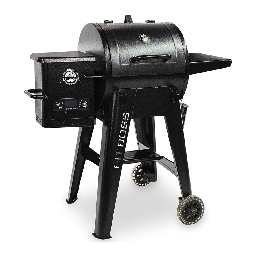
| MODEL | UNIT ASSEMBLED (WxHxD) | UNIT WEIGHT | COOKING AREA | TEMP. RANGE | DIGITAL FEATURES | |
| PB | PB550G | 1,227mm x 1,195mm x 868mm / 48.3" x 47" x 34.17" | 55.7 kg / 122.8 lb | Main - 2580.6 cm² / 400 sq. in. Upper Rack - 920 cm² / 142.6 sq. in. TOTAL - 3500.6 cm² / 542.6 sq. in. | 82-260°C / 180-500°F | Ten temperature presets, start-up and cool-down cycles, electric igniter |
PARTS

ASSEMBLY PREPARATION
Parts are located throughout the shipping carton, including underneath the grill. Inspect the grill, parts, and hardware blister pack after removing from the protective shipping carton. Discard all packaging materials from inside and outside of the grill before assembly, then review and inspect all parts by referencing the parts list. If any part is missing or damaged, do not attempt to assemble. Shipping damage is not covered under warranty. Contact your dealer or Pit Boss® Customer Care for parts.
www.pitboss-grills.com

To ease installation and avoid injury, use two people when assembling this appliance.
Tools required for assembly: screwdriver and level.

Tools not included.
ASSEMBLY INSTRUCTIONS
It is advised to read each step entirely before starting assembly on instructions. Do not tighten screws completely until all screws for that step have been installed. Hardware combination involving a locking washer and washer should be installed with the locking washer closest to the head of the screw.
SECURING FEET TO SUPPORT LEGS

Parts Required:
- 1 x Left Front Leg (#9)
- 1 x Left Back Leg (#10)
- 1 x Left Front Leg Trim Piece (#13)
- 1 x Left Back Leg Trim Piece (#14)
- 6 x Screw (#D)
Installation:
- Use three screws to attach the Left Front Leg Trim Piece to the Left Front Leg. Continue to install the Left Back Leg and Left Back Leg Trim Piece.
SECURING SUPPORT PLATES

Parts Required:
- 1 x Left Front Leg (#9)
- 1 x Left Back Leg (#10)
- 1 x Left Bottom Support Plate (#17)
- 1 x Short Support Plate (#18)
- 8 x Screw (#D)
Installation:
- Install one Short Support Plate to the side of the unit between of a Front and Back Support Legs using four screws. Repeat the same installation to mount the Bottom Support Plate to the same legs.
NOTE: Make sure Bottom Support Plate is facing up with correct direction.
SECURING SUPPORT PLATES AND WHEELS

Parts Required:
- 1 x Right Front Leg (#11)
- 1 x Right Back Leg (#12)
- 1 x Right Bottom Support Plate (#16)
- 1 x Short Support Plate (#18)
- 2 x Wheel (#15)
- 8 x Screw (#D)
- 2 x Wheel Axle Pin (#E)
- 2 x Wheel Cotter Pin (#F)
- 2 x Wheel Washer (#G)
Installation:
- Install one Short Support Plate to the side of the unit between of a Front and Back Support Legs using four screws. Repeat the same installation to mount the Bottom Support Plate to the same legs.
- Attach the large Wheel to the Support Leg by inserting the Wheel Axle Pin through the Wheel Support Leg hole, then secure using the Wheel Cotter Pin. Repeat installation for other Wheel on the same side.
NOTE: Make sure Bottom Support Plate is facing up with correct direction.
SECURING SUPPORT PLATE TO SUPPORT LEGS FOR WHEELS

Parts Required:
- 2 x Front/Back Long Support Plate (#19)
- 4 x Screw (#D)
Installation:
- Secure one Long Support Plate to one Support Leg for Wheel using two screws. Ensure the flat side of the Support Plate is facing outwards. Repeat the same installation to mount the other Long Support Plate to the other Support Leg.
SECURING SUPPORT PLATE TO SUPPORT LEGS

Parts Required:
- 4 x Screw (#D)
Installation:
- Next, Secure the Long Support Plates to the Support Legs. Secure using two screws for each plate.
MOUNTING MAIN BARREL TO THE CART

Parts Required:
- 1 x Main Barrel (#4)
- 12 x Screw (#A)
- 12 x Washer (#B)
- 12 x Locking Washer (#C)
- 1 x Power Cord (#29 or 30)
- 1 x Cable Clip (#28)
Installation:
NOTE: There are two Power Cords supplied. Select the Power Cord that is required for your region.
- Place the cable clips on the correct power cord. Insert the power cord into the grove at the bottom of the hopper. Secure the cable clip to the bottom of the hopper with the previously installed screw. Note Illustration 6A.
- Prepare the Main Barrel to be mounted to the cart. Carefully, lift the Cart into an upright position with the Wheels on the bottom. Position the Cart next to the Main Barrel, with both facing the same direction. Using a second person, prepare to lift the Main Barrel onto the Cart. With one person lifting from the hopper side, and the other person lifting from the opposing barrel end, carefully lift the Main Barrel, and slowly lower onto the cart. Note illustration 6B.
- Next, open the Main Barrel lid. Adjust the rotation as needed to align the screw holes of the Main Barrel to the Cart. Once placed, secure each leg to the Main Barrel using three Screws, Washers, and Locking Washers. Note illustration 6C.
INSTALLING THE LID STOPPER

Parts Required:
- 1 x Lid Stopper (#1)
Installation:
- Secure the Lid Stopper onto the top of the Main Barrel using the preinstalled screw on top of the Main Barrel.
INSTALLING THE LID HANDLE

Parts Required:
- x Lid Handle (#2)
- x Lid Handle Bezel (#3)
Installation:
- Remove the pre-installed screws from the Lid Handle. From inside the barrel lid, insert one screw protrude to the outside. Add a Bezel on the screw. Then hand-tighten the screw (from the inside) into the Lid Handle. Repeat for other side.
INSTALLING THE FLAME BROILER COMPONENTS

Parts Required:
- 1 x Flame Broiler Main Plate (#8)
- 1 x Flame Broiler Slider (#7)
Installation:
- Insert the Flame Broiler Main Plate into the main grill. Rest the Flame Broiler Main Plate on the built-in ledge (on the inside right) of the main grill that directs grease towards the grease bucket spout. Slide the entire piece to the left side, and the two slots on the Flame Broiler Main Plate will fit into the rounded ledge above the burn pot. It will sit slightly at a downward angle. Note illustration 9A.
If the Main Plate is resting on the base of the Barrel, it is installed incorrectly. Poor installation may result in damage to your Main Grill Barrel.
- Place the Flame Broiler Slider on top of the Flame Broiler Main Plate covering the slotted openings. Ensure the raised tab is on the left and the two pins at the bottom of the Flame Broiler Slider place into the holes of the Flame Broiler Main Plate to easily adjust for direct and indirect flame when cooking. Both flame broiler parts are lightly coated with oil to avoid rusting when shipped. Note illustration 9B.
NOTE: To maintain the searing and grilling performance of your cooking grids, regular care and maintenance Is required. See Owner's Manual.
INSTALLING FLAME BROILER ADJUSTING BAR

Parts Required:
- 1 x Flame Broiler Adjusting Bar (#5)
- 1 x Flame Broiler Adjusting Bar Handle (#6)
Installation:
- Insert the Flame Broiler Adjusting Bar through the opening hole on the left side of the Main Barrel. Add the Flame Broiler Adjusting Bar Handle on the end outside the barrel. Next, slide the notched end of the Adjusting Bar into the locking tab on the Flame Broiler Slider, giving you adjustable access to the Flame Broiler Slider on the Main Plate.
INSTALLING THE SIDE SHELF

Parts Required:
- 1 x Right Side Table (#24)
- 2 x Screw (#A)
- 2 x Washer (#B)
- 2 x Locking Washer (#C)
Installation:
- Loosen the two pre-installed screws from the side of the Main Barrel. Hook up the Right Side Table on the screws first then secure the two pre-loosened screws into place.
- From underneath, secure the Right Side Table to the side panel of the Main Barrel using two screws, washers, and locking washers.
SECURING THE FRONT SHELF BRACKETS

Parts Required:
- 1 x Front Shelf Bracket Right (#21)
- 1 x Front Shelf Bracket Left (#22)
- 4 x Screw (#A)
- 4 x Washer (#B)
- 4 x Locking Washer (#C)
Installation:
- Secure each Front Shelf Support Bracket onto the Front Support Leg by using two screws, washers and locking washers.
INSTALLING THE FRONT SHELF

Parts Required:
- 1 x Front Shelf (#20)
Installation:
- Place the Front Shelf on the Front Shelf Support Brackets. Note illustration 13A as unfolded Front Shelf.
- Note illustration 13B as folded Front Shelf.
- Front Shelf can also be placed on the Bottom Support Plates and be used as Bottom Plate. Note illustration 13C.
INSTALLING THE GRILL COOKING COMPONENTS

Parts Required:
- 2 x Cooking Grids (#25)
- 1 x Warming Rack (#26)
Installation:
- Place the Cooking Grids, side by side, on the grid ledge inside the Main Grill.
- Place the Upper Warming Rack on the upper ledge inside the Main Grill.
The Warming Rack will lock into place.
INSTALLING THE GREASE BUCKET

Parts Required:
- 1 x Grease Bucket (#23)
Installation:
- Place the Grease Bucket on the spout hook on the end of the Main Barrel. Ensure it is level to avoid grease spills.
- The unit is now completely assembled.
CONNECTING TO A POWER SOURCE

NOTE: Before plugging your Pit Boss® into any electrical outlet, ensure the temperature dial is in the OFF position.
- TANDARD OUTLET
This appliance requires 220-240 volts, 50Hz, 250w service. It must be a grounded plug.
Disconnect unit from power source when not in use.
Refer to Owner's Manual for Operating Instructions

Documents / Resources
References
Download manual
Here you can download full pdf version of manual, it may contain additional safety instructions, warranty information, FCC rules, etc.
Download Pit Boss 550 Navigator, PB550G - Grill and Smoker Series Manual
Advertisement


Need help?
Do you have a question about the 550 Navigator and is the answer not in the manual?
Questions and answers