Table of Contents
Advertisement
Quick Links
CDD4 Duct Carbon Dioxide Transmitter
Introduction
The CO2 transmitter uses Infrared Technology to monitor
CO2 levels and outputs a linear 4-20 mA or 0-5/0-10 Vdc
signal. Options include an LCD, a control relay and a
resistive temperature sensor. Features include a back-lit
LCD and user menu for easy installation.
Before Installation
Read these instructions carefully before installing and
commissioning the CO2 transmitter. Failure to follow
these instructions may result in product damage. Do not
use in an explosive or hazardous environment, with
combustible or flammable gases, as a safety or emergency
stop device or in any other application where failure of the
product could result in personal injury. Take electrostatic
discharge precautions during installation and do not exceed
the device ratings.
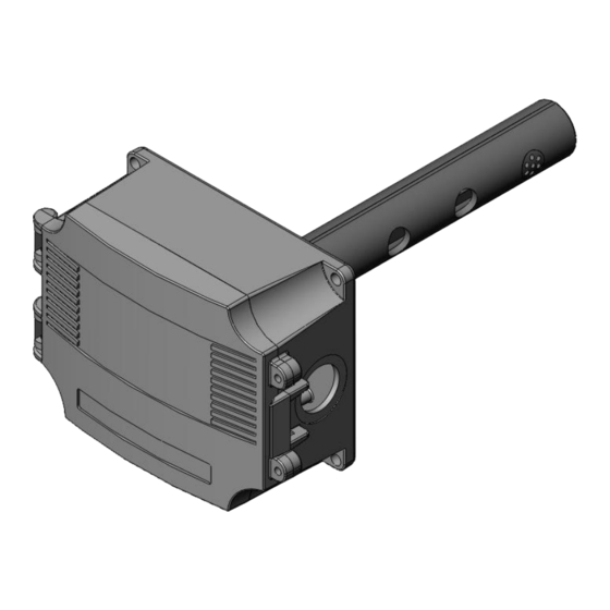
Mounting
The CO2 duct type sensor installs on the outside of a
return air duct with the sampling tube inserted into the
duct. Use the included foam plug to prevent air from
entering the enclosure through the conduit and causing an
incorrect reading.
Mount the sensor in an easily accessible location in a
straight section of duct at least five feet from corners and
other items that may cause disturbances in the air flow.
Avoid areas where the detector is exposed to vibrations or
rapid temperature changes.
The duct CO2 transmitter principal of operation is based
on the Venturi effect of the probe that extends into the
HVAC duct. Air flowing through the duct is forced into
the vent holes on one side of the probe, into the enclosure,
over the CO2 sensor and then the air is drawn back out of
the enclosure via the vent holes on the opposite side of the
probe.
May 27, 2013
Drill or punch a 1-1/8" or 1-1/4" hole in the duct at the
preferred location and insert the probe into the hole to
mark the enclosure mounting holes. Remove the unit and
drill the four mounting holes. Clean all drilled holes of
debris before mounting the device. Mount the enclosure to
the duct with four sheet metal screws such that the duct air
flow is parallel with the vent holes in the probe (i.e.: air
flows directly into the probe holes). To prevent air leaks,
ensure the gasket is compressed around the probe between
the device enclosure and the air duct.
Open the cover by releasing the latch and connect the
device according to the wiring instructions. After wiring
and setup are complete, close and latch the cover. Secure it
with two self-tapping screws in the holes provided.
1
Installation Manual
Advertisement
Table of Contents

Related Manuals for Greystone Energy Systems CDD4


Summary of Contents for Greystone Energy Systems CDD4
- Page 1 CDD4 Duct Carbon Dioxide Transmitter Installation Manual Drill or punch a 1-1/8” or 1-1/4” hole in the duct at the preferred location and insert the probe into the hole to mark the enclosure mounting holes. Remove the unit and drill the four mounting holes. Clean all drilled holes of debris before mounting the device.
- Page 2 CDD4 Duct Carbon Dioxide Transmitter Installation Manual all control applications and is available on the TEMP SENSOR terminals. Typical 4-20 mA wiring with 24 Vdc and all options Wiring Deactivate the 24 Vac/dc power supply until all connections are made to the device to prevent electrical shock or equipment damage.
- Page 3 CDD4 Duct Carbon Dioxide Transmitter Installation Manual Start-up Verify the device is properly wired and connections are Ensure the device has been operating normally for at least tight. Ensure the V/I switch is set for the correct signal five minutes before applying gas. Turn the valve knob on type.
- Page 4 CDD4 Duct Carbon Dioxide Transmitter Installation Manual Setup Menu The menu has several items shown below. Some items change depending on the hardware configuration and the CO2 sensor. To enter the menu, press and release the <MENU> key while in normal operation. This will enter the SETUP menu step 1, pressing <MENU>...
- Page 5 CDD4 Duct Carbon Dioxide Transmitter Installation Manual This item is omitted if the 2000 ppm sensor is installed 9. Calibrat This item is used for 0 ppm gas calibration and is explained in the Calibration section. 0 PPM <MENU> 10. Calibrat This item is used for 1000 ppm gas calibration and is explained in the Calibration section.
- Page 6 CDD4 Duct Carbon Dioxide Transmitter Installation Manual LCD Display Resolution ....1 ppm CO2 Size ..... 1.4” w x 0.6” h (35 x 15 mm) alpha-numeric 2 line x 8 characters Backlight .
Need help?
Do you have a question about the CDD4 and is the answer not in the manual?
Questions and answers