Table of Contents
Advertisement
Quick Links
Installation, Operation, and Maintenance
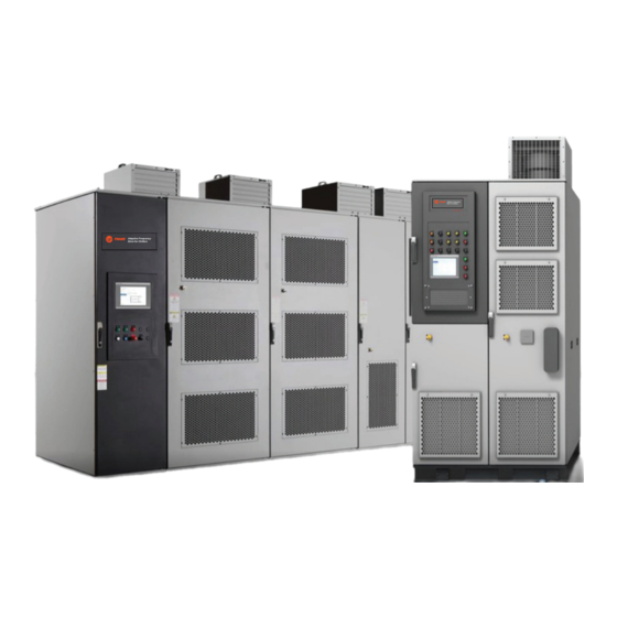
Remote-Mounted Medium Voltage
Air-Cooled Adaptive Frequency™
Drive with Tracer AdaptiView™
Control
VFDB
Model:
Only qualified personnel should install and service the equipment. The installation, starting up, and servicing of
heating, ventilating, and air-conditioning equipment can be hazardous and requires specific knowledge and training.
Improperly installed, adjusted or altered equipment by an unqualified person could result in death or serious injury.
When working on the equipment, observe all precautions in the literature and on the tags, stickers, and labels that are
attached to the equipment.
March 2023
Adaptive Frequency
TM
Drive for Chillers
SAFETY WARNING
VFDB-SVX001C-EN
Adaptive Frequency
TM
Drive for Chillers
Advertisement
Table of Contents

Related Manuals for Trane VFDB


Summary of Contents for Trane VFDB
- Page 1 Adaptive Frequency Drive for Chillers Adaptive Frequency Drive for Chillers VFDB Model: SAFETY WARNING Only qualified personnel should install and service the equipment. The installation, starting up, and servicing of heating, ventilating, and air-conditioning equipment can be hazardous and requires specific knowledge and training.
- Page 2 When working with or around hazardous chemicals, these compounds have the same potential impact to the ALWAYS refer to the appropriate SDS and OSHA/GHS environment. Trane advocates the responsible handling of all (Global Harmonized System of Classification and refrigerants-including industry replacements for CFCs and Labeling of Chemicals) guidelines for information on HCFCs such as saturated or unsaturated HFCs and HCFCs.
- Page 3 Copyright This document and the information in it are the property of Trane, and may not be used or reproduced in whole or in part without written permission. Trane reserves the right to revise this publication at any time, and to make changes to its content without obligation to notify any person of such revision or change.
-
Page 4: Table Of Contents
Anchoring ......38 VFDB Checks ......8 Load Cable Connections . - Page 5 PowerFlex 7000 (Model: AFDJ) PowerFlex 6000T (Model: VFDB) ..1 Instructions ......2 PowerFlex “A”...
-
Page 6: Overview
For variable frequency drives instructions: Unless specified otherwise, disconnect all or other energy storing components provided by Trane electrical power including remote disconnect and or others, refer to the appropriate manufacturer’s... -
Page 7: Ce For Mv Drives
Any Ethernet cables 6. Check to assure incoming power to the drive is phased A, being used by the customer to interface with the Trane chiller B, C. must be shielded Ethernet cabling. -
Page 8: Visual Inspection
Return all interlocks to operation when the start-up is inspection for the following: completed. – Shipping damage 4. Check to see that the VFDB is properly ground to earth. – Moisture (or indications of moisture) Refer to “Grounding the Cabinet,” p. 42 “Input Power,... -
Page 9: Rockwell Medium Voltage Powerflex 6000T Drives
Cabinet Voltage Levels your local Trane or Rockwell office. Typical Configurations WARNING The Trane-supplied Medium Voltage VFDB drives include two Hazardous Voltage! parts: input starter and drive panel. The drive panel is available Failure to follow instructions below could result in in two air-cooled versions, called Frames: death, serious injury. -
Page 10: Control Voltage Power De-Energization
For variable frequency drives serious injury. or other energy storing components provided by Trane Technicians, in order to protect themselves from or others, refer to the appropriate manufacturer’s... -
Page 11: Back-Feed Sources Of Hazardous Electrical Energy
Note: For questions regarding these procedures, contact your local Trane or Rockwell office. • Back-feed power caused by a fan that rotates from ambient wind blowing on it, electric motor(s) rotating when... -
Page 12: General Information
Rockwell provides drive-size order-specific literature that or service for the drive. When ordering parts, contact the local ships with the drive from the Rockwell factory. Trane Parts Office in your area. For service, contact a qualified service organization. Cabinet Servicing... -
Page 13: About The Vfdb Drive
Altitude: 3300 feet (1000 m) above sea level without derating. Drive Identification The drive has a Trane model number and a Rockwell series number. Both these are extremely important when identifying the drive for service or parts. Refer to “Model Number Descriptions,”... -
Page 14: Model Number Descriptions
Model Number Descriptions Trane Service Model Digit 15 — VFD Frame Size (SRRL) Number An example of a typical chiller starter model number is: VFDB0035NA0B00CDA Model Number Digit Identification Model number digits are selected and assigned in accordance with the... -
Page 15: Cabinet
Environmental Conditions Ensure the equipment room addresses the heat rejections requirements. Important: Location of the VFDB drive is important if proper performance and operating life is to be • Be sure the enclosure is installed in a non-corrosive expected. Therefore, unless designated for... - Page 16 5. Maximum cable information refer to Table 2 Table 3 Shipping Note • Mounted on a (500 lb [226.8 kg] max) wooden skid with provisions for a fork truck. Lifting means also supplied on top. VFDB-SVX001C-EN...
- Page 17 11.71 44.21 44.21 49.21 49.21 5.02 CONTROL WIRE 5.02 CONTROL WIRE 59.1 59.1 CONDUIT OPENING CONDUIT OPENING (3.93X3.93) (3.93X3.93) LINE CABLE CONDUIT OPENING LOAD CABLE CONDUIT OPENING 8.96 (17.1X11.8) 11.71 44.21 49.21 5.02 CONTROL WIRE 59.1 CONDUIT OPENING (3.93X3.93) VFDB-SVX001C-EN...
- Page 18 CUT OUT (5.51X17.72) CONTROL WIRE CONDUIT OPENING (3.94X4.92) 5.31 59.1 11.81 16.73 LINE CABLE CONDUIT OPENING 6.89 (9.84X7.87) 10.02 19.64 LOAD CABLE CONDUIT OPENING (9.84X7.87) 45.45 50.80 SERVICE CUT OUT (5.51X17.72) CONTROL WIRE CONDUIT OPENING 5.31 59.1 (3.94X4.92) 11.81 VFDB-SVX001C-EN...
- Page 19 Cabinet Figure 4. A-Frame: Front view (VFD 2300/3300/4160V), in. 15.75 15.75 22.05 18.51 1U,1V,1W T1,T2,T3 DISPLAY HAZARDOUS 91.65 91.65 VOLTAGE LABEL GROUND BAR 47.64 63.39 15.75 22.05 91.65 75.20 VFDB-SVX001C-EN...
- Page 20 Cabinet Figure 5. A-Frame: Front view (VFD 6600V), in. 15.75 21.54 1U,1V,1W T1,T2,T3 DISPLAY 91.65 HAZARDOUS VOLTAGE LABEL GROUND BAR 90.94 87.01 15.75 21.54 91.65 110.04 VFDB-SVX001C-EN...
- Page 21 CROSS POWER WIRING - REFER TO FIELD WIRING DIAGRAM. (CONDUIT IS RECOMMENDED). y CROSS CONTROL WIRING - REFER TO FIELD WIRING DIAGRAM. (CONDUIT IS RECOMMENDED). y INPUT STARTER - CAN BE PLACED ON RIGHT OR LEFT SIDE OF THE DRIVE. VFDB-SVX001C-EN...
- Page 22 LINE CABLE CONDUIT OPENING (15.75X5.51) 104.13 76.57 55.02 33.46 CONTROL 5.91 WIRE CONDUIT OPENING (3.94X4.13) 49.21 50.21 47.20 41.45 12.89 5.12 LOAD CABLE MOUNTING HOLES FOR CONDUIT OPENING 0.71(18.0) DIA. ANCHOR BOLTS 7.58 (15.75X5.51) 16.02 LINE CABLE CONDUIT OPENING (15.75X5.51) VFDB-SVX001C-EN...
- Page 23 INPUT STARTER NOTES : y CROSS POWER WIRING - REFER TO FIELD WIRING DIAGRAM. y CROSS CONTROL WIRING - REFER TO FIELD WIRING DIAGRAM. y INPUT STARTER - CAN BE PLACED ON RIGHT OR LEFT SIDE OF THE DRIVE. VFDB-SVX001C-EN...
- Page 24 90 MAX DOOR SWING H MAX 90 MAX 90 MAX DOOR OPENING DOOR SWING DOOR SWING VFD 2300/3300/4160V 34.73 MAX 90 MAX DOOR OPENING DOOR SWING 90 MAX 90 MAX 90 MAX DOOR SWING DOOR SWING DOOR SWING VFD 6600V VFDB-SVX001C-EN...
- Page 25 Cabinet Figure 10. A-Frame: Interior view, major components, in. VFDB-SVX001C-EN...
- Page 26 (5.4X5.4) CONTROL WIRE CONDUIT OPENING (5.4X5.4) LOAD CABLE CONDUIT 6.30 OPENING (5.4X5.4) 140.94 59.1 143.70 62.99 35.04 42.91 LINE CABLE 47.05 CONDUIT 55.12 OPENING (5.4X5.4) CONTROL WIRE CONDUIT OPENING LOAD (5.4X5.4) CABLE CONDUIT 6.30 OPENING (5.4X5.4) 152.76 59.1 155.51 VFDB-SVX001C-EN...
- Page 27 Cabinet Figure 12. B-Frame: Front view, in. 15.75 18.50 DISPLAY 91.65 HAZARDOUS VOLTAGE LABEL GROUND BAR 149.61 15.75 18.50 1U,1V,1W 91.65 T1,T2,T3 161.42 VFDB-SVX001C-EN...
- Page 28 0.72(18) DIA. ANCHOR BOLTS 143.76 97.08 61.69 65.20 31.48 33.23 1.26 1.26 LINE CABLE CONDUIT OPENING (5.4X5.4) LOAD CABLE CONDUIT OPENING 55.12 CONTROL (5.4X5.4) WIRE CONDUIT OPENING (5.4X5.4) 19.49 11.28 9.16 6.10 153.09 MOUNTING HOLES FOR 0.72(18) DIA. ANCHOR BOLTS 155.57 VFDB-SVX001C-EN...
- Page 29 Figure 14. B-Frame: Door-swing requirements, in. 90.0 MAX 90.0 MAX DOOR SWING DOOR SWING 90.0 MAX 90.0 MAX 90.0 MAX DOOR SWING DOOR SWING DOOR SWING 39.45 MAX 90.0 MAX DOOR OPENING DOOR SWING Figure 15. B-Frame: Interior view, major components VFDB-SVX001C-EN...
- Page 30 6.61 5.41 LINE CABLE CONDUIT OPENING (5.68X9.00) 4.64 16.04 30.00 LOAD CABLE CONDUIT OPENING (5.68X9.00) 3.62 CONTROL WIRE CONDUIT OPENING (3.00X3.00) Figure 17. Input starter: Front view, in. 2.48 1.00(25.0)x3.00(76.0) NON-REMOVABLE SILL CHANNELS 90.24 COPPER ONLY LABLE 1U,1V,1W 25.98 VFDB-SVX001C-EN...
- Page 31 4.45 20.12 32.95 30.00 35.98 LOAD CABLE 4.62 CONDUIT OPENING (5.68X9.00) CONTROL WIRE CONDUIT OPENING (3.00X5.00) 2.30 MOUNTING HOLES FOR 0.50(12.0) DIA, ANCHOR BOLTS 23.68 25.98 Figure 19. Input starter: Door-swing requirements, in. DOOR SWING 23.5 MAX DOOR OPENING VFDB-SVX001C-EN...
- Page 32 Cabinet Figure 20. Input starter: Interior view, major components VFDB-SVX001C-EN...
-
Page 33: Pre-Installation
Drives may contain heavy components that are mounted for vertical shift. Tilting can cause heavy items to shift. Lift the Power Module/LV Control Cabinet Depending on the type of drive frame, or lifting angles must be installed before you can lift the cabinet. VFDB-SVX001C-EN... - Page 34 1. Remove the lifting angles from the skid. 2. Align and secure the lifting angles in four places as shown in below figure. VFDB-SVX001C-EN...
-
Page 35: Lift Input Starter
Power Supply). If the storage temperature fluctuates significantly or if the relative humidity exceeds 95%, use heating and moisture protection devices to prevent condensation. Store the drive in a conditioned building with adequate air circulation. Do not store the drive outdoors. VFDB-SVX001C-EN... -
Page 36: Mechanical Installation
Extra cable hole locations allow for added installation flexibility. Front Front Side View 3. Secure the cabinets together using M6 and M8 hardware. Open the doors to access front edge joining holes (four or five places). VFDB-SVX001C-EN... -
Page 37: Affix Cabinets To Floor
Each weld location should be 3.9 in. (100 mm) for every 39.4 in. (1000 mm). See Mounting Requirements in the PowerFlex 6000T Drives Shipping and Handling Manual, publication 6000-PC100 for further information on the steel base and desired trench and mounting customer-specifications. VFDB-SVX001C-EN... -
Page 38: Install Input Starter
10. Reverse procedure after cables have been installed. fasteners 180 degree in a counterclockwise direction. Figure 32. Power bus with barrier removed Figure 30. Low voltage panel Remove 1/4 turn fasteners Low Voltage Panel Power Bus Remove self- tapping screws VFDB-SVX001C-EN... -
Page 39: Load Cable Connections
7. Reinstall the current transformer barrier and reassemble after siting the drive. the cabinet 1. Place the fan housing on the top plate of the drive, making sure that the socket is on the same side as the aviation plug. VFDB-SVX001C-EN... -
Page 40: Install The Cooling Fan For A-Frame Drives (6.6 Kv)
Figure 37. Main cooling fan housing, A-frame (6...6.6 kV) Fan wiring terminals located behind this cover Mount fan assembly with M6 hardware across the front of the fan assembly Front View Back flange of fan Top plate bracket assembly Back View VFDB-SVX001C-EN... -
Page 41: Wiring
Table 4. Wire sizing reference inadvertently energized. For variable frequency drives or other energy storing components provided by Trane AWG/MCM equivalent or others, refer to the appropriate manufacturer’s literature for allowable waiting periods for discharge of 0.32... -
Page 42: Torquing Electrical Power Connections
MUST follow requirements for inadvertently energized. For variable frequency drives field wiring installation and grounding as described in or other energy storing components provided by Trane NEC and your local/state/national electrical codes. or others, refer to the appropriate manufacturer’s... - Page 43 Wiring Figure 38. Motor terminal connection MEDIUM VOLTAGE (2300-6600V) VFDB, RATR, RPIR, RXL, CSOL, CATR, CPIR, CXL OR CVAC VFDB-SVX001C-EN...
- Page 44 Wiring Figure 39. RAFD (VFDB) MV drive field connection diagram 1. Line power 5. HPC Interlock 2. Motor-to-drive power – For medium voltage drives, Dry contact 14 AWG max wire size. 3. Cross power wiring 6. Oil pump interlock 4. Chiller control power 7.
- Page 45 Figure 41. PowerFlex 6000T: Scope of input voltages to/from drive Line Line Supply Supply Motor Motor Input Input Drive Panel Drive Panel Starters Starter PowerFlex 6000T Frame A PowerFlex 6000T Frame B See sales order for line voltage and other options. VFDB-SVX001C-EN...
-
Page 46: Detailed Field Wiring Points
1X1-10 to 9A Wire #6F 1A7-J2-2 to 10A Wire #10A 1X1-21 to 10A Wire #53F Remote stop interlock (Must be jumpered if not used) 2436 2437 Refer to the chiller Installation, Operation, and Maintenance manual for chiller control wiring requirements. VFDB-SVX001C-EN... - Page 47 • Route control and power wiring separately. The distance between the control cable tray and power cable tray must be 11.8 in (300 mm) minimum. • Do NOT mix AC and DC wires within the same cable bundle. VFDB-SVX001C-EN...
-
Page 48: Pre-Commissioning Start-Up
Drive Commissioning Prior to pre-commissioning start-up, it is imperative for Rockwell and Trane to receive a completed copy of the Power 1. A pre-installation meeting with the customer to review: Flex “A” or “B” Frame Pre-Commissioning Check List as soon •... -
Page 49: Start-Up Test Log
Pre-Commissioning Start-Up Start-Up Test Log Note: Trane recommends setting. Start-Up Test Log Complete the start-up test log (see 49) upon chiller drive commission by Rockwell. It is recommended that you retain a copy for future reference. Water-Cooled CenTraVac Chiller with Tracer AdaptiView Control and Adjustable Frequency Drive (AFD) Starter... -
Page 50: Maintenance
Causes could be corrosion, excessive temperature, or find that the interval can be lengthened. contamination. • Check for any visual/physical evidence of damage or degradation of components in the medium voltage VFDB-SVX001C-EN... -
Page 51: Chiller Operator Display Content
Check all labels for readability. If any labels are unreadable, damaged, or missing, contact Rockwell Automation for replacements. Chiller Operator Display Content Refer to Operations Guide: Tracer AdaptiView™ Display for Water-Cooled CenTraVac™ Chillers (CTV-SVU01*-EN, or the most recent version) for Tracer AdaptiView display information. VFDB-SVX001C-EN... -
Page 52: Troubleshooting
This information can be verified off of the chiller nameplate, and by referring to this manual. a. DO NOT cycle unit power or reset the controls. Leave the AFD and the Symbio 800 in their present states. 2. Collect Chiller Information. VFDB-SVX001C-EN... - Page 53 10216 troubleshooting of the drive and chiller. Contact your local AFD Motor Current Overload HW OverCurrent 10093 Trane Service agency to request service and/or additional AFD Instantaneous Current U0-U8/V0-V8/W0-W8 IGBT 12150 support. Trane can contact the appropriate technical service Overload Overcurrent group for additional support if necessary.
-
Page 54: Led Usage
Powercell / Transfomer Over AFD Over Temperature 12218 Temperature Green Processing message Processing Powercell / Transfomer Over Not processing AFD Over Temperature 12230 Temperature Bus error Bus Error Powercell / Transfomer Over AFD Over Temperature 12231 Normal operation Temperature VFDB-SVX001C-EN... - Page 55 Troubleshooting Color Indication Green Normal operation Bus Ready Bus timeout error Bus not running Configuration switch error HW Status VFDB-SVX001C-EN...
- Page 56 Troubleshooting Page left intentionally blank VFDB-SVX001C-EN...
-
Page 57: Powerflex "A" Or "B" Frame Pre-Commissioning Check List
PowerFlex “A” or “B” Frame Pre-Commissioning Check List Remote-Mounted Medium Voltage Air-Cooled Adaptive Frequency™ Drives: PowerFlex 7000 (Model: AFDJ) PowerFlex 6000T (Model: VFDB) WARNING Safety Alert! Failure to follow instructions below could result in death or serious injury. In addition to the following tasks, you MUST: •... -
Page 58: Instructions
Instructions It is imperative for Rockwell and Trane to receive the following check list information filled out as soon as possible and sent to Rockwell Medium Voltage Center of Expertise in Cambridge, Ontario, Canada office and to the regional Trane Technical Support Team to assure scheduling is not a problem (see contact information below for more information). -
Page 59: Powerflex "A" Or "B" Frame Pre-Commissioning Check List
The field service agency and Rockwell are to also coordinate the visit with La Crosse CTV Technical Service. PowerFlex “A” or “B” Frame Pre-Commissioning Check List Please complete (print) this Pre-Commissioning Check List and when complete, fax or e-mail to Rockwell and Trane (contact information provided on preceding page): Required:... - Page 60 Bolts have been inserted into original location on top of drive (leakage of cooling air). All contactors and relays have been operated manually to verify free movement. For model 7000, frame A only, install neutral resistors. Not applicable for PF6000T model VFDB. 3. Safety Initials Date ...
- Page 61 5. Power Wiring Initials Date The power cable connections to the drive, motor and isolation transformer adhere to CEC, NEC, IEC, or appropriate local standards and/or regulation. Note: To be completed by Electrical Contractor. The cable terminations, if stress cones are used, adhere to the appropriate standards. ...
- Page 62 For more information, please visit trane.com or tranetechnologies.com. Trane has a policy of continuous product and product data improvement and reserves the right to change design and specifications without notice. We are committed to using environmentally conscious print practices.
- Page 63 Notes VFDB-SVX001C-EN...
- Page 64 For more information, please visit trane.com or tranetechnologies.com. Trane has a policy of continuous product and product data improvement and reserves the right to change design and specifications without notice. We are committed to using environmentally conscious print practices.
Need help?
Do you have a question about the VFDB and is the answer not in the manual?
Questions and answers