
Related Manuals for Trane VariTrane VAV Series


Summary of Contents for Trane VariTrane VAV Series
- Page 1 Installation/ Operator Maintenance VariT rane™ Single-Duct and Fan-Powered Units All VariTrane VAV Models with pneumatic, electronic, DDC controls and diffusers. VAV-SVN01E-EN June 2006...
- Page 2 © 2006 American Standard All rights reserved VAV-SVN01E-EN...
-
Page 3: Table Of Contents
Contents Service Model Number Description ....4 – 14 General Information ..........15 Literature Contents Receiving and Handling Warnings and Cautions Explanations Unit Information ..........16 – 17 Single-Duct Units Dual-Duct Units Fan-Powered and Low-Height Units Unit Installation ..........18 – 31 Hanging Bracket Locations Unit Weights Water Coil Connections... -
Page 4: Service Model Number Description
Fiberglass Wool! FM00 FM – Customer-supplied Digit 1, 2—Unit Type actuator & controller VariTrane single-duct WARNING: ALL INSULATED UNITS FM01 FM – Trane actuator w/ cusomer- (except closed-cell foam insulation) Digit 3—Reheat supplied control CONTAIN FIBERGLASS WOOL! Read Cooling Only VMA1 FM –... - Page 5 Service Model Number Description Single-Duct Units (con't.) Digit 17—Not Used Digit 23—Transformer Digit 27 , 28, 29—Electric Heat kW None None 120/24 volt (50 VA) 0.5 kW Digit 18—Not Used 208/24 volt (50 VA) 1.0 kW 240/24 volt (50 VA) 1.5 kW Digit 19—Outlet Plenum (Connection is 277/24 volt (50 VA)
- Page 6 Digit 1, 2, 3—Unit Type FM00 FM – Customer-supplied slip & drive) actuator & controller VariTrane dual-duct none FM01 FM – Trane actuator w/ Digit 4—Development Sequence customer-supplied controller 1 outlet–RH Sixth 1 outlet–END PC03 PN – N.C. heating/ N.O. cooling Digit 5, 6—Primary Air Valve...
- Page 7 None Electric Heat FM00 FM customer actuator & control 1-Row–Plenum inlet installed RH Hot Water Heat FM01 FM Trane actuator w/ customer- 2-Row–Plenum inlet installed RH Digit 4—Development Sequence supplied controller 1-Row–Discharge installed, LH Sixth VMA2 FM Johnson Controls 1-Row–Discharge installed, RH...
- Page 8 Service Model Number Description Fan-Powered Parallel Units (con't) Digit 30—Electric Heat Stages None 1 Stage 2 Stages Equal 3 Stages Equal Digit 31—Contactors None 24-volt magnetic 24-volt mercury PE with magnetic PE with mercury Digit 32—Airflow Switch None With VAV-SVN01E-EN...
- Page 9 Slip & Drive FM00 FM customer actuator & control Digit 5, 6—Primary Air Valve Digit 20—Attenuator FM01 FM Trane actuator w/ customer- 4" inlet (225 max cfm) None supplied controller 5" inlet (350 max cfm) With VMA2 FM Johnson controls VMA-1420 6"...
- Page 10 Service Model Number Description Fan-Powered Series Units (con't) Digit 27 , 28, 29—Electric Heat Kilowatts None 0.5 kW 1.0 kW 1.5 kW 24.0 kW Digit 30—Electric Heat Stages None 1 Stage 2 Stages Equal 3 Stages Equal Digit 31—Contactors None 24-volt magnetic 24-volt mercury PE with magnetic...
- Page 11 Hot Water Heat Flanged FM00 FM customer actuator & control Slip & Drive Digit 4—Development Sequence FM01 FM Trane actuator w/ customer- Digit 20—Not Used Sixth supplied controller Digit 5, 6—Primary Air Valve VMA2 FM Johnson Controls VMA- Digit 21—Water Coil...
- Page 12 Service Model Number Description Fan-Powered Low-Height Parallel Units (con't) Digit 27 , 28, 29—Electric Heat Voltage Digit 30—Electric Heat Stages None None 0.5 kW 1 Stage 1.0 kW 2 Stages Equal 1.5 kW Digit 31—Contactors 2.0 kW None 2.5 kW 24-volt magnetic 3.0 kW 24-volt mercury...
- Page 13 Hot Water Heat 347/60/1 FM00 FM customer actuator & control 230/50/1 Digit 4—Development Sequence FM01 FM Trane actuator w/ customer- Digit 19—Outlet Connection Sixth supplied controller Flanged VMA2 FM Johnson controls VMA-1420 Digit 5, 6—Primary Air Valve Slip &...
- Page 14 Service Model Number Description Fan-Powered Low-Height Series Units (con't) Digit 27 , 28, 29—Electric Heat Voltage Digit 30—Electric Heat Stages None None 0.5 kW 1 Stage 1.0 kW 2 Stages Equal 1.5 kW Digit 31—Contactors 2.0 kW None 2.5 kW 24-Volt magnetic 3.0 kW 24-Volt mercury...
-
Page 15: General Information
This manual describes the installation heating coils, water valves, etc. Also contact you local Trane representative of VariTrane VAV units with recom- check that the unit voltages agree with immediately. -
Page 16: Unit Information
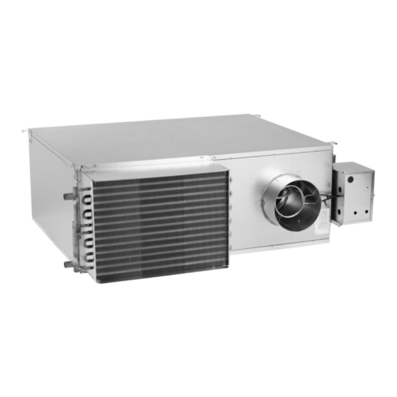
Unit Information Single-Duct Units Figure 1 – Typical Single-Duct Units Dual-Duct Units The basic unit consists of a sheet metal Dual-duct units provide two air valves: casing with an air valve, which is used one as heating primary air and the to modulate the air being delivered into other as cooling primary air. - Page 17 Unit Information Fan-Powered and Fan-Powered VariTrane fan-powered unit fan sizes Low-Height Units 02SQ–05SQ and 08SQ–10SQ were performance tested at .12 in. w.g. and VariTrane fan-powered and low-height sizes 06SQ and 07SQ were tested at .15 fan-powered units can be either parallel in.
-
Page 18: Unit Installation
Unit Installation Dual-Duct Due to their weight, the VAV terminal units should be suspended from the Dual-duct units should be supported by uppermost ceiling, independent of the either hanger straps or by using a false ceiling grid. Suspension devices threaded rod in conjunction with the are to be supplied by the installer. - Page 19 Unit Installation Fan-Powered (Standard and Low- Figure 6 Height) Fan-powered units should be sup- Parallel Hanger Bracket Locations Sizes ported by either hanger straps or by using a threaded rod in conjunction with the hanger brackets that are provided on the unit. Care should be Water Coil exercised to insure that the hanging...
- Page 20 Unit Installation Figure 7 Series Hanger Bracket Locations Flow Ring Tubing Valve Optional Attenuator Field Installed Airflow TOP VIEW Plenum Inlet Series Cooling & Hot Water Fan Inlet w/o Attenuator All attenuators are the same length and width. Sizes 01 and 02 units are smaller than attenuators. Water Coil 1.625"...
- Page 21 Unit Installation Figure 8 Low-Height Parallel 08SQ/09SQ w/ Hot Water or Electric Heat 31.65" (804 mm) Airflow Plenum Inlet 13.00" 23.90" (330 mm) (607 mm) Primary Airflow 19.86" Optional Attenuator (504 mm) Field Installed 24.30" (617 mm) 3.35" Airflow (85 mm) TOP VIEW Discharge Outlet 23.10"...
- Page 22 Unit Installation Figure 9 Low-Height Parallel10SQ 1.625" 38.95" (41 mm) (989 mm) Primary Flow Ring Airflow Tubing Plenum Inlet Valve 5.625" (143 mm) 38.75" (984 mm) 5.625" Terminal Box Optional Heater (143 mm) Airflow Discharge Outlet 41.137" (1045 mm) TOP VIEW VAV-SVN01E-EN...
- Page 23 Unit Installation Figure 10 Low-Height Series 08SQ/09SQ w/ Hot Water or Electric Heat 31.65" (804 mm) Airflow 10.13" 12.85" Plenum Inlet (257 mm) (326 mm) 4.00" (102 mm) Primary Airflow 19.86" Optional Attenuator Field Installed (504 mm) Valve 3.35" (85 mm) 34.30"...
- Page 24 Unit Installation Figure 11 Low-Height Series 10SQ w/ Hot Water or Electric Heat 19.45" 19.45" 10.12" (494 mm) (494 mm) (257 mm) 31.65" 31.65" (804 mm) (804 mm) Optional Attenuator Optional Attenuator Field Installed Field Installed Primary Airflow 19.86" 19.86" Airflow Airflow 3.35"...
- Page 25 Unit Installation Figure 12 Attenuator Installation—Parallel Units 1. Attach attenuator to unit as shown with provided mounting brackets. MOUNTING BRACKET OPTIONAL ATTENUATOR FIELD INSTALLED Note: Bottom bracket not shown. Bottom bracket to be installed in same orientation on bottom of unit. VAV-SVN01E-EN...
- Page 26 Unit Installation Figure 13 Attenuator Installation—Series Units 1. Attach attenuator to unit as shown with provided mounting brackets. MOUNTING BRACKET OPTIONAL ATTENUATOR FIELD INSTALLED Note: Bottom bracket not shown. Bottom bracket to be installed in same orientation on bottom of unit. VAV-SVN01E-EN...
- Page 27 Unit Installation Figure 14 Attenuator Installation—Low-Height Parallel Units 1. Attach attenuator to unit as shown with provided mounting brackets. MOUNTING BRACKET OPTIONAL ATTENUATOR FIELD INSTALLED Note: Bottom bracket not shown. Bottom bracket to be installed in same orientation on bottom of unit. VAV-SVN01E-EN...
- Page 28 Unit Installation Figure 15 Attenuator Installation—Low-Height Series Units 1. Attach attenuator to unit as shown with provided mounting brackets. MOUNTING BRACKET OPTIONAL ATTENUATOR FIELD INSTALLED MOUNTING BRACKET OPTIONAL ATTENUATOR FIELD INSTALLED OPTIONAL ATTENUATOR FIELD INSTALLED MOUNTING BRACKET Note: Bottom bracket not shown. Bottom bracket to be installed in same orientation on bottom of unit. VAV-SVN01E-EN...
- Page 29 Unit Installation Chart 1 – Unit Weights Single-Duct Units Unit VCCF VCCF w/ VCEF VCEF w/ VCWF VCWF VCWF 1-Row VCWF 2-Row Size Dual Wall Dual Wall 1-Row 2-Row w/ Dual Wall w/ Dual Wall (lbs/kg) (lbs/kg) (lbs/kg) (lbs/kg) (lbs/kg) (lbs/kg) (lbs/kg) (lbs/kg)
- Page 30 Unit Installation Chart 1 – Unit Weights (Con't.) Series Fan-Powered Unit VSCF VSCF w/ VSEF VSEF w/ VSWF VSWF VSWF 1-Row VSWF 2-Row VSxF Size Dual Wall Dual Wall 1-Row 2-Row w/ Dual Wall w/ Dual Wall Attenuator (lbs/kg) (lbs/kg) (lbs/kg) (lbs/kg) (lbs/kg)
-
Page 31: Dual-Duct Units
Care should be taken to properly Actuator Mounting support the water coil piping All VariTrane units should be provided Trane offers a factory-mounted actuator connections while connecting the with a minimum of 1.5-duct diameters with a 90-second drive time. The adjoining pipe. -
Page 32: Unit Setup
Unit Setup Chart 2 – Flow Sensor Delta P vs. Airflow Delivery 8" x 12" 10" 8" 12" 14" 16" 16" x 24" 0.01 1,000 10,000 Airflow (CFM) Chart 3– Fan Motor Amperage Maximum PSC Fan Motor Amperage (FLA) Maximum ECM Fan Motor Amperage (FLA) Size Size Parallel/Series 02SQ... - Page 33 (SCR) Motor Speed Control Figure 17 – Internal Potentiometer Electrically Commutated Motor (ECM) Adjustment Procedure. Trane offers an energy efficient ECM In order to make units more convenient motor as a motor option. Balancing of and efficient to balance, an SCR...
- Page 34 Unit Setup Chart 4 – VPxF 03SQ ECM CFM Table VPxF 03SQ Motor Min CFM: 160 Motor Max CFM: 1085 TENS UNITS TENS UNITS L/sec Setting Switch Switch L/sec Setting Switch Switch 1001 1010 1020 1029 1038 1048 1057 1066 1076 1085 VAV-SVN01E-EN...
- Page 35 Unit Setup Chart 5 – VPxF 04SQ ECM CFM Table VPxF 04SQ Motor Min CFM: 220 Motor Max CFM: 1510 TENS UNITS TENS UNITS L/sec Setting Switch Switch L/sec Setting Switch Switch 1002 1015 1028 1041 1054 1067 1080 1093 1106 1119 1132...
- Page 36 Unit Setup Chart 6 – VPxF 05SQ ECM CFM Table VPxF 05SQ Motor Min CFM: 280 Motor Max CFM: 1850 TENS UNITS TENS UNITS L/sec Setting Switch Switch L/Sec Setting Switch Switch 1073 1089 1105 1120 1136 1152 1168 1184 1200 1216 1231...
- Page 37 Unit Setup Chart 7 – VPxF 06SQ ECM CFM Table VPxF 06SQ Motor Min CFM: 530 Motor Max CFM: 2100 TENS UNITS TENS `UNITS L/sec Setting Switch Switch L/sec Setting Switch Switch 1323 1339 1355 1370 1386 1402 1418 1434 1450 1466 1481...
- Page 38 Unit Setup Chart 8 – VSxF 03SQ ECM CFM Table VSxF 03SQ Motor Min CFM: 200 Motor Max CFM: 1100 TENS UNITS TENS UNITS L/sec Setting Switch Switch L/sec Setting Switch Switch 1000 1009 1018 1027 1036 1045 1055 1064 1073 1082 1091...
- Page 39 Unit Setup Chart 9– VSxF 04SQ ECM CFM Table VSxF 04SQ Motor Min CFM: 275 Motor Max CFM: 1500 TENS UNITS TENS UNITS L/sec Setting Switch Switch L/sec Setting Switch Switch 1005 1018 1030 1042 1055 1067 1079 1092 1104 1117 1129 1141...
- Page 40 Unit Setup Chart 10– VSxF 05SQ ECM CFM Table VSxF 05SQ Motor Min CFM: 350 Motor Max CFM: 2050 TENS UNITS TENS UNITS L/sec Setting Switch Switch L/sec Setting Switch Switch 1209 1226 1243 1260 1277 1295 1312 1329 1346 1363 1380 1398...
- Page 41 Unit Setup Chart 11– VSxF 06SQ ECM CFM Table VSxF 06SQ Motor Min CFM: 700 Motor Max CFM: 2500 TENS UNITS TENS UNITS L/sec Setting Switch Switch L/sec Setting Switch Switch 1609 1627 1646 1664 1682 1700 1718 1736 1755 1773 1791 1809...
- Page 42 Unit Setup Chart 12– LPxF 08SQ ECM CFM Table LPxF 08SQ Motor Min CFM: 100 Motor Max CFM: 460 TENS UNITS TENS UNITS L/sec % Setting Switch Switch L/sec Setting Switch Switch VAV-SVN01E-EN...
- Page 43 Unit Setup Chart 13– LPxF 09SQ ECM CFM Table LPxF 09SQ Motor Min CFM: 250 Motor Max CFM: 1025 TENS UNITS TENS UNITS L/sec Setting Switch Switch L/sec Setting Switch Switch 1002 1009 1017 1025 VAV-SVN01E-EN...
- Page 44 Unit Setup Chart 14– LSxF 08SQ ECM CFM Table LSxF 08SQ Motor Min CFM: 100 Motor Max CFM: 460 TENS UNITS TENS UNITS L/sec Setting Switch Switch L/sec Settings Switch Switch VAV-SVN01E-EN...
- Page 45 Unit Setup Chart 15– LSxF 09SQ ECM CFM Table LSxF 09SQ Motor Min CFM: 240 Motor Max CFM: 950 TENS UNITS TENS UNITS L/sec Setting Switch Switch L/sec Setting Switch Switch VAV-SVN01E-EN...
- Page 46 Unit Setup Chart 15– LSxF 10SQ ECM CFM Table LSxF 10SQ Motor Min CFM: 400 Motor Max CFM: 1800 TENS UNITS TENS UNITS L/sec Setting Switch Switch L/sec Setting Switch Switch 1107 1121 1135 1150 1164 1178 1192 1206 1220 1234 1249 1263...
-
Page 47: Wiring Diagrams
Wiring Diagrams Figure 19 – Single-Duct Units (Electronic or DDC/UCM) Line Voltage L1 L2 N - 480 (See Nameplate) L1 L2 - 208, 240 SINGLE DUCT UNITS - ELECTRONIC OR DDC/UCM - L1 N - 277, 347 HEATER TERMINALS - TYPICAL OF SINGLE PHASE VOLTAGES SINGLE PHASE Manual Reset... - Page 48 Wiring Diagrams Figure 20 – Single-Duct Units (Pneumatic Controls) SINGLE DUCT UNITS - PNEUMATIC CONTROL - L1 L2 - 208, 240 Line Voltage L1 L2 N - 480 HEATER TERMINAL - TYPICAL OF SINGLE PHASE VOLTAGES (See Nameplate) L1 N - 277, 347 L1 N SINGLE PHASE...
- Page 49 Wiring Diagrams Figure 21 – Fan-Powered Units (Electronic or DDC/UCM) Line Voltage (See Nameplate) L1 L2 N - 208, 240, 480 FAN-POWERED UNITS - ELECTRONIC OR DDC/UCM - L1 N - 277, 347 HEATER TERMINALS - TYPICAL OF SINGLE PHASE VOLTAGES L1 L2 N SINGLE PHASE...
- Page 50 Wiring Diagrams Figure 22 – Fan-Powered Units (Pneumatic Controls) FAN-POWERED UNITS - PNEUMATIC CONTROL - L1 L2 N - 208, 240, 480 HEATER TERMINAL - TYPICAL OF SINGLE PHASE VOLTAGES Line Voltage L1 N - 277, 347 (See Nameplate) L1 L2 SINGLE Manual Reset PHASE...
- Page 51 Wiring Diagrams Figure 23 – Fan-Powered Control Boxes Fan-powered Control Box Fan-powered Control Box with Electronic or DDC Controls with Pneumatic Controls LINE VOLTAGE Duct Pressure Switch Option LINE VOLTAGE OR FROM HEATER TERMINAL OR FROM HEATER TERMINAL GREEN GREEN GROUND GROUND SCREW...
- Page 52 Wiring Diagrams Figure 24 – Fan-Powered Units with ECM Fan-powered Control Box w/ ECM with Electronic or DDC Controls (Depending on the size of the unit, the ECM board may or may not be located in the fan control box.) Fan-powered Control Box w/ ECM with Pneumatic Controls Duct Pressure Switch Option LINE VOLTAGE...
- Page 53 Wiring Diagrams Figure 25 – Fan-Powered Low-Height Units Fan-Powered Low-Height Control Box with Electronic or DDC Controls CAPACITOR MOTOR 2 (SIZE 10 ONLY) Fan-Powered Low-Height Control Box with Pneumatic Controls MOTOR CAPACITOR Duct Pressure Switch Option LINE VOLTAGE OR FROM HEATER TERMINAL CAPACITOR MOTOR 2 (SIZE 10 ONLY)
- Page 54 Wiring Diagrams Figure 26 – Fan-Powered Low-Height Units with ECM Fan-Powered Low-Height Control Box w/ ECM with Electronic or DDC Controls Fan-Powered Low-Height Control Box w/ ECM with Pneumatic Controls (Depending on the size of the unit, the ECM board may or may not be located Duct Pressure Switch Option in the fan control box.) LINE VOLTAGE...
- Page 55 Maintenance Figure 27 – Standard Motor Removal Figure 28 – Low-Height Motor Removal Periodic maintenance of the VariTrane product is minimal, but necessary for efficient operation. Routine mainte- nance consists of inspecting/replacing the air filters of the fan-powered terminals. Motors Both the PSC (permanent split capaci- tor) and the ECM (Electrically Commu- tated Motor) require no lubrication...
-
Page 56: Installation Of Diffusers
Installation of Diffusers General Figure 29 – Diffuser Installation in T-Bar Drywall/Plaster Ceiling Ceiling All units must be installed upright and Finish installation of diffusers in plaster level as indicated by the arrow on the ceiling. Follow these procedures before side of the units. - Page 57 Maintenance/ Service Log Date T ag Serial # Service Notes VAV-SVN01E-EN...
- Page 58 Maintenance/ Service Log Date T ag Serial # Service Notes VAV-SVN01E-EN...
- Page 59 Notes VAV-SVN01E-EN...
- Page 60 Inland An American Standard Company www.trane.com Trane has a policy of continuous product and product data improvement and reserves the right to change For more information contact design and specifications without notice. Only qualified technicians should perform the installation and your local district office or servicing of equipment referred to in this publication.
Need help?
Do you have a question about the VariTrane VAV Series and is the answer not in the manual?
Questions and answers