Table of Contents
Advertisement
Quick Links
Instructions – Parts List
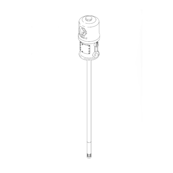
75:1 Fire-Ballr 425 Pumps
For pumping non–corrosive and non–abrasive
greases and lubricants only.
100 psi (0.7 MPa, 7 bar) Maximum Air Input Pressure
7500 psi (52 MPa, 517 bar) Maximum Working Pressure
Model No. 239729, Series B
120 lb (55 kg) drum length
Model No. 239730, Series B
400 lb (180 kg) drum length
Model No. 239731, Series B
stubby length
Important Safety instructions
Read all warnings and instructions in this manual.
Save these instructions.
WARNING
This pump is designed to be used only in pumping
non-corrosive and non-abrasive oils and lubricants.
Any other use of the pump can cause unsafe oper-
ating conditions and component rupture, which can
result in fluid injection, other serious injury, or fire or
explosion.
GRACO INC. P.O. BOX 1441 MINNEAPOLIS, MN 55440-1441
Copyright 2001, Graco Inc. is registered to I.S. EN ISO 9001
308777 rev.H
Model 239730 Shown
06306B
Advertisement
Table of Contents

Subscribe to Our Youtube Channel
Related Manuals for Graco 239729


Summary of Contents for Graco 239729
- Page 1 Model 239730 Shown 06306B GRACO INC. P.O. BOX 1441 MINNEAPOLIS, MN 55440-1441 Copyright 2001, Graco Inc. is registered to I.S. EN ISO 9001...
-
Page 2: Table Of Contents
D Read all instruction manuals, tags, and labels before operating the equipment. D Use the equipment only for its intended purpose. If you are not sure, call your Graco distributor. D Do not alter or modify this equipment. Use only genuine Graco parts and accessories. - Page 3 WARNING SKIN INJECTION HAZARD Fluid from the valve, leaks, or ruptured components can inject fluid into your body and cause ex- tremely serious injury, including the need for amputation. Fluid splashed in the eyes or on the skin can also cause serious injury. D Fluid injected into the skin is a serious injury.
- Page 4 D The air motor exhausts any fluids added to the input air. D Graco does not manufacture or supply the reactive chemical components that may be used in this equipment and is not responsible for injury or property loss, damage, expense or claims (direct or consequential) that arise from the use of such chemical components.
- Page 5 Notes 308777H...
-
Page 6: Installation
D To maintain grounding continuity when flushing or NOTE: Always use genuine graco parts and accesso- relieving pressure, hold a metal part of the dispens- ries, available from your Graco distributor. ing valve firmly to the side of a grounded metal pail, then trigger the gun. - Page 7 Connect a grounded dispensing hose (F) to the selecting and installing system components and acces- 3/8 npt(f) pump outlet. Install an appropriate gun or sories. Contact your Graco distributor for assistance in dispensing valve (G) to the hose. designing a system to suit your particular needs.
-
Page 8: Operation
Operation Startup and Adjustment WARNING D This pump is designed to be used ONLY in Open the bleed-type master air valve. Open the pumping non-corrosive and non-abrasive lubri- dispensing valve and slowly open the air regulator until cants and greases. Any other use of this pump the pump is running smoothly. -
Page 9: Troubleshooting
Troubleshooting Before servicing this equipment always make sure to WARNING Relieve the Pressure. To reduce the risk of serious injury whenever you are instructed to relieve pressure, always follow the Note: Check all possible problems and solutions Pressure Relief Procedure on page 8. before disassembling the pump. - Page 10 Displacement Pump Service Lips of v-packings must face up. Ref. No. 63 (copper gasket) and Torque to 50 to 70 ft-lb Ref. No. 60} (cotter pin), see (68 to 95 NSm). Parts Drawing on page 16. } Included in Repair Kit 239734, which may be purchased separately.
- Page 11 Displacement Pump Service 5. Place the riser tube (80) in a vise, and remove the WARNING piston assembly. Remove the packing housing (70) from the riser tube, and remove the packings To reduce the risk of serious injury whenever you from the housing.
- Page 12 Air Motor and Throat Service Before you Start 4. Remove the eight screws (7) holding the cylinder (32) to the base (56). Carefully pull the cylinder D Be sure you have all necessary parts on hand. Air straight up off the piston. See Fig. 4. Motor Repair Kit 207385 includes repair parts for the motor.
- Page 13 Air Motor and Throat Service 6. Grip the toggle rockers (16) with a pliers. Com- NOTE: To remove the exhaust valve poppets press the springs (17) and swing the toggle (38*), stretch them out and cut with a sharp knife. assembly (K) up and away from the piston lugs 8.
- Page 14 Air Motor and Throat Service Reassembly Throat Packing Service 1. Clean all the parts carefully in a compatible solvent WARNING and inspect for wear or damage. Use all the repair kit parts during reassembly and replace other parts The piston in the air motor, located behind the air as necessary.
- Page 15 Air Motor and Throat Service 9. Reinstall the spacer and packing in the base and CAUTION packing nut (45{). Screw the packing nut into the base, and tighten it securely. Carefully slide the When reinstalling cotter pin (60}), always spread piston rod (52) down through the throat packing, and flatten the pin (both the head and prongs) and lower the piston into the base.
-
Page 16: Parts Drawing
Parts Drawing Torque to 45–55 ft–lb (61–75 N–m) 308777H... -
Page 17: Parts List
Parts List Model 239729, Series B 120-lb (55 kg) drum length Model 239730, Series B 400-lb (180 kg) drum length Model 239731, Series B stubby length Air Motor Pump Part No. Description Qty. Part No. Description Qty. 100170 BALL, steel; 3/8” dia. -
Page 18: Dimensions
41.25” 855 mm 678 mm 1048 mm 48–3/16” (1224 mm) 1/2 npt(f) 1/2 npt(f) air inlet air inlet 06306 Model 239729, Series B Model 239730, Series B 3/8 npt fluid outlet 14–9/16” (369.9 mm) 6.5” 32–1/16” (165.1 mm) 814 mm 17.5”... -
Page 19: Mounting Hole Layout
Weight Model 239729 ................ -
Page 20: Warranty
With the exception of any special, extended, or limited warranty published by Graco, Graco will, for a period of twelve months from the date of sale, repair or replace any part of the equipment determined by Graco to be defective.
Need help?
Do you have a question about the 239729 and is the answer not in the manual?
Questions and answers