
Related Manuals for Next Level Racing FLIGHT SEAT PRO


Summary of Contents for Next Level Racing FLIGHT SEAT PRO
- Page 1 T A K E I T T O T H E S K I E S Video Instruction: bit.ly/nlrbuild FLIGHT SEAT INSTRUCTION MANUAL *ELECTRONICS NOT INCLUDED...
- Page 2 You’ll be setting yourself up for success by following the instruction booklet to fully optimize your product. N E X T L E V E L R A C I N G . C O M ASSEMBLY VIDEO bit.ly/nlrbuild @next_level_racing @nextlevelracingOfficial @nextlvlracing Next Level Racing FOLLOW support@nextlevelracing.com...
- Page 3 Video Instruction: bit.ly/nlrbuild support@nextlevelracing.com PRE-FLIGHT IN THE CHECKS *NOT TO SCALE WARNING (LEFT) (LEFT) (RIGHT) (RIGHT) • Please do not use power tools for assembly as over tightening can damage parts. • If you require further support, consult the installation video or contact us at support@nextlevelracing.com 1 x LEFT FRAME MEMBER 1 x LEFT SIDE PANEL •...
-
Page 4: Table Of Contents
Video Instruction: bit.ly/nlrbuild support@nextlevelracing.com KEY STEPS MOUNTING LOCATION DIAGRAMS page 8 Hotas Plate page 8 Flight Plate page 9 1 x SEAT BOTTOM 1 x SEAT BACKREST 2 x MOTION V3 MOUNTING ARM 1 x SEAT BELT Mouse Plate page 10 5 x M8 20mm SOCKETHEAD BOLTS GENERAL ASSEMBLY page 12... -
Page 5: Hotas Plate
Video Instruction: bit.ly/nlrbuild support@nextlevelracing.com MOUNTING LOCATIONS HOTAS PLATE FLIGHT PLATE PRODUCT LEGEND: Logitech G X56 Throttle/HOTAS Logitech G X52 Throttle/HOTAS TMT.16000M / TCA Sidestick Airbus PRODUCT LEGEND: TM HOTAS Warthog Stick / Winwing HOTAS Orion 2 TM HOTAS Warthog Duel Throttle / Winwing Orion 2 Throttle TM HOTAS Warthog Stick / Winwing HOTAS Orion 2 TM TCA Quadrant Airbus Edition Throttle VKB Gunfighter PRO MK.II... -
Page 6: Mouse Plate
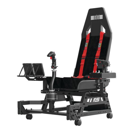
Video Instruction: bit.ly/nlrbuild support@nextlevelracing.com MOUSE PLATE ADJUSTMENT POINTS The Flight Seat Pro is a fully adjustable cockpit making it perfect for flight enthusiasts of all sizes. Utilize the various adjustment points to achieve your desired position. FLIGHT SEAT MOUSE PLATE... - Page 7 Video Instruction: bit.ly/nlrbuild support@nextlevelracing.com PARTS: PARTS: • • 1 x Left Frame Member • • 1 x Right Frame Member • • 1 x H Frame (LEFT) (RIGHT) • • 1 x End Panel • • 4 x M8 55mm Sockethead Bolts •...
- Page 8 Video Instruction: bit.ly/nlrbuild support@nextlevelracing.com PARTS: PARTS: • • 2 x M8 16mm Sockethead Bolts • • 1 x Seat Bottom • • 2 x M8 Washers • • 1 x Seat Backrest WARNING: Ensure you are firmly holding the Recliner before lifting the adjustment lever to avoid injury.
- Page 9 Video Instruction: bit.ly/nlrbuild support@nextlevelracing.com PARTS: PARTS: • • 1 x Telescoping Outer Arm • • 1 x Telescoping Inner Arm • • 4 x M8 16mm Sockethead Bolts • • 2 x M8 16mm Sockethead Bolts • • 2 x M8 Washers •...
-
Page 10: Extended Hotas Mount Installation
Video Instruction: bit.ly/nlrbuild support@nextlevelracing.com PARTS: PARTS: • • 4 x M8 16mm Sockethead Bolts • • 2 x Plastic Caps • • 4 x M8 Washers Align the mounting slots on the HOTAS Extension Adjustment Bracket assembly with the threaded Align the Plastic Caps with the Bolt cut-outs on the Frame Members and press them on to fit. -
Page 11: Centre Pole Bracket Adjustment
Video Instruction: bit.ly/nlrbuild support@nextlevelracing.com PARTS: PARTS: CENTRE POLE BRACKET ADJUSTMENT • • NIL • • 1 x Centre Pole Bracket • • 1 x M8 60mm Sockethead Bolt • • 2 x M8 12mm Knobs • • 3 x M8 Washers •... - Page 12 Uninstall 2 x Rear Castor Wheels and Square Washers from the Flight Stand Pro Assembly. PARTS: • • NIL A) Uninstall 4 x Bolts and Washers securing the Steel Safety Caps to the Flight Seat Pro Frame. Remove the Plastic Caps. B) Uninstall the 2 x Steel Safety Caps.
-
Page 13: Seat Belt Installation
PARTS: PARTS: • • NIL • • NIL Align the slots on the Frame of the Flight Seat Pro to the threaded inserts on the Frame of the Flight Re-install Plastic Caps previously uninstalled in Step 33a. Stand Pro. PARTS:... -
Page 14: Motion Plus Platform Installation
Video Instruction: bit.ly/nlrbuild support@nextlevelracing.com MOTION PLUS PLATFORM PARTS: INSTALLATION • • NIL Repeat on Other Side A) Uninstall 2 x M8 Bolts and Washers securing the H Frame to the Frame. B) Align the Seat Belt end plates to the mounting holes on the Frame. PARTS: PARTS: LOWER FLIGHT ARM ASSEMBLY... -
Page 15: Buttkicker Pole Installation
Video Instruction: bit.ly/nlrbuild support@nextlevelracing.com PARTS: BUTTKICKER POLE INSTALLATION PARTS: (SKIP TO STEP 44 FOR MOTION V3 PLATFORM INSTALLATION) • • 1 x Buttkicker Pole • • NIL • • 2 x M8 60mm Sockethead Bolts • • 2 x M8 Washers Note: The Buttkicker pole can be •... -
Page 16: Seat Belt Installation
Video Instruction: bit.ly/nlrbuild support@nextlevelracing.com PARTS: PARTS: • • 4 x M8 16mm Sockethead Bolts • • NIL • • 4 x M8 Washers WARNING: The NLR Motion V3 is heavy and will require 2 people to install the setup. A) Bolt through the front mounting holes of the Motion V3 platform and secure with 2 x M8 Bolts and Washers. Align the Motion V3 unit with the mounting holes on the Frame. -
Page 17: Flight Arm Adjustment
Video Instruction: bit.ly/nlrbuild support@nextlevelracing.com PARTS: PARTS: FLIGHT ARM ADJUSTMENT • • NIL • • NIL Front View Install the HOTAS Mount Assembly to the H Frame. Please refer to Step 24 to 27 for HOTAS Mount Loosen the Bolts on the Flight Arm Assembly, adjust to the desired position and tighten the Bolts to secure. - Page 18 Video Instruction: bit.ly/nlrbuild support@nextlevelracing.com FLIGHT SEAT PRO FLIGHT SEAT PRO ENTRY LEVEL UPGRADE PATH ADVANCED UPGRADE PATH NLR Free Standing Keyboard & Mouse Stand NLR HF8 Haptic Gaming Pad NLR Flight Stand Pro NLR Free Standing Keyboard & Mouse Stand...
- Page 19 32 – Reportez-vous à l’image. Désinstallez les 2 roues pivotantes arrière et les rondelles carrées de l’ensemble Flight Stand Pro. 33 – Reportez-vous à l’image. A) Désinstallez 4 boulons et rondelles fixant les capuchons de sécurité en acier au cadre Flight Seat Pro. Retirez les capuchons en plastique. B) Désinstallez les 2 capuchons de sécurité en acier.
- Page 20 33 – Fare riferimento all’immagine. A) Disinstallare i 4 bulloni e le rondelle che fissano i cappucci di sicurezza in acciaio al telaio Flight Seat Pro. Rimuovere i tappi di plastica. B) Disinstallare i 2 tappi di sicurezza in acciaio.
- Page 21 29 – Siehe Bild. A) Lösen Sie die Schrauben, mit denen die HOTAS-Winkelhalterung an der Mittelstangenhalterung befestigt ist. B) Stellen Sie den gewünschten Winkel ein und ziehen Sie die Schrauben fest, um ihn zu sichern. 33 – Consulte la imagen. A) Desinstale los 4 pernos y arandelas que sujetan las tapas de seguridad de acero al armazón Flight Seat Pro. Retire las tapas de plástico. B) Desinstale las 2 tapas de seguridad de acero.
- Page 22 32 – 画像を参照して ください。 Flight Stand Pro アセンブリから 2 x リア キャスター ホイールとスクエア ワッシャーを取り外します。 33 – Consulte a imagem. A) Desinstale 4 parafusos e arruelas que prendem as tampas de segurança de aço à estrutura do Flight Seat Pro. Remova as tampas plásticas. B) Desinstale as 2 tampas de segurança de aço.
- Page 23 35 – Resme bakın. Daha önce Adım 33a’da kaldırılan Cıvatalar ve Pullar ile cıvatalayın ve sabitleyin. Diğer tarafta tekrarlayın. 31 – См. изображение. A) Снимите сборку поворотного кронштейна и сборку центральной стойки HOTAS с рамы стенда Flight Stand Pro. B) Снимите узел пластины для мыши и узел центральной стойки HOTAS с рамы кресла Flight Seat Pro.
- Page 24 28 – Patrz ilustracja. A) Poluzuj pokrętła mocujące wspornik środkowego słupka do środkowego mocowania słupka. B) Ustaw żądany kąt i dokręć pokrętła, aby zabezpieczyć. 31 – Viz obrázek. A) Odmontujte sestavu otočného letového ramene a sestavu středové tyče HOTAS z rámu stojanu Pro. B) Odmontujte sestavu desky myši a sestavu středové tyče HOTAS z rámu sedadla Flight Seat Pro.
- Page 25 31 - زكرم دومع ةعومجمو ، راودلا ناريطلا عارذ ةعومجم تيبثت ءاغلإب مق )أ .ةروصلا ىلإ عوجرلاHOTAS راطإ نمFlight Stand Pro. زكرم دومع ةعومجمو ، سواملا ةحول ةعومجم تيبثت ءاغلإب مق )بHOTAS راطإ نمFlight Seat Pro.
- Page 26 support@nextlevelracing.com support@nextlevelracing.com...
Need help?
Do you have a question about the FLIGHT SEAT PRO and is the answer not in the manual?
Questions and answers