Orbis DICROMAT+, DICROMAT 2+ Proximity Switch Instructions Manual
- User instructions (2 pages)
Advertisement
- 1 Overview of the device
- 2 DESCRIPTION
- 3 BOX CONTENTS
- 4 INSTALLATION
- 5 ASSEMBLY
- 6 PUTTING INTO SERVICE. ADJUSTMENTS
- 7 SETTING THE DETECTION FIELD
- 8 DETECTION INDICATORS
- 9 SETTING THE BRIGHTNESS (only in master sensor)
- 10 SETTING THE DISCONNECTION DELAY (only in master sensor)
- 11 TECHNICAL CHARACTERISTICS
- 12 DIMENSIONS
- 13 SENSOR WIRING DIAGRAM
- 14 Documents / Resources
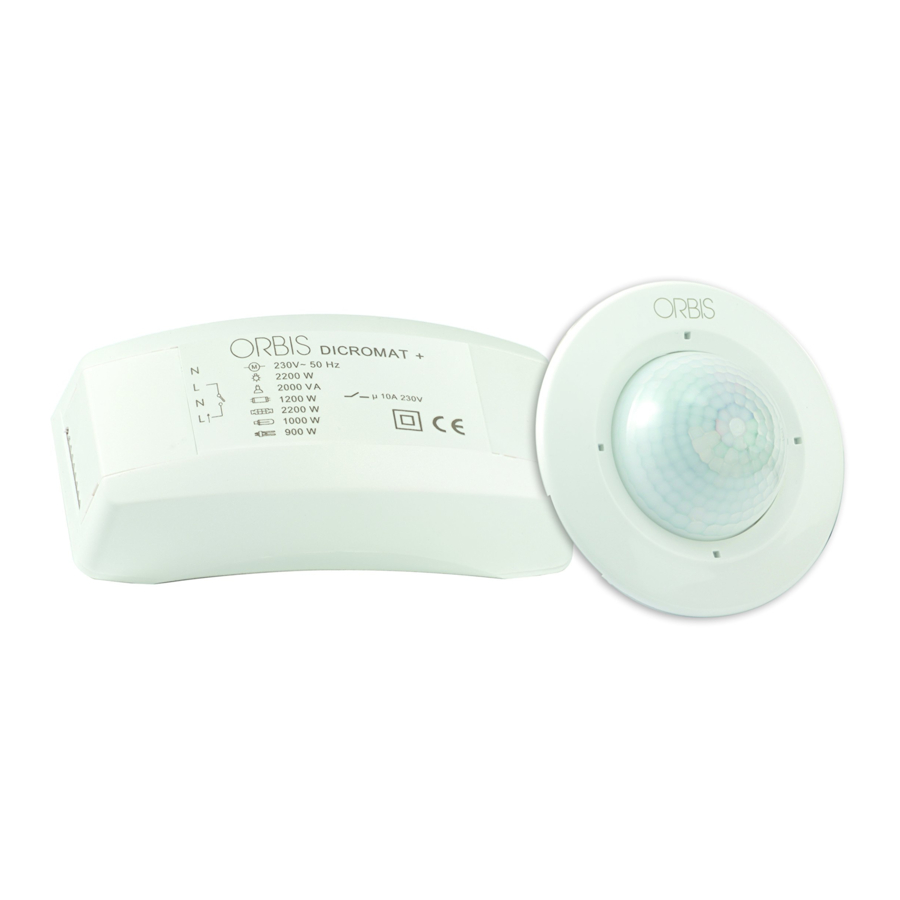
Overview of the device

DESCRIPTION
The DICROMAT + proximity switch detects the invisible infrared emissions coming from people and other heat sources without emitting any type of radiation.
In the DICROMAT + several movement detection sensors (additional sensors) can be connected to a single power supply module.
When a heat source moves under any sensor of the proximity switch, its output circuits are enabled, and when it stops detecting movement they are disabled after a delay time adjustable only in the master sensor.
The DICROMAT + circuit, as well as circuit 1 of the DICROMAT 2+, only react when the light conditions are below the level selected in the master sensor. Circuit 2 of the DICROMAT 2+ always reacts independently of the regulated brightness. The DICROMAT + is not suitable for alarm systems.
BOX CONTENTS
- 1 power supply module
- 1 master sensor.
- 1 extension cable of 50 cm for sensors.
- 1 detection area delimiter.
INSTALLATION

The installation and assembly of electric appliances should be carried out by an authorized installer.
The appliance is internally protected against interference by a safety circuit. Nevertheless, some particularly strong electromagnetic fields can manage to alter its operation, therefore it should not be mounted near inductive loads (motors, transformers, etc.).
In the DICROMAT + installation it should be kept in mind that the detection takes place when crossing its detection beams, and therefore if the heat source to be detected is in parallel with the beams (not crossing them), it will detect it at a smaller distance, since it does not cross the beams until it is very near the sensor.
In this figures, the arrow indicates the direction the person or object to detect is moving in.

The ambient temperature of the enclosure where the DICROMAT + is installed has a significant influence on the detection sensitivity and therefore on the detection distance. The sensitivity is less at higher temperatures since the appliance works with the movement of a heat source. The nearer the ambient temperature is to 36 ºC (in most cases 36 ºC is the temperature of the human body), the worse is the detection.
Fog or rain can impair the detection field. Clothing reduces the heat contribution to the enclosure and so diminishes the detection sensitivity.
If two DICROMATS + are connected in the same enclosure, the lamp powered by one of them should not be in the detection field of the other.
ASSEMBLY
Embedded in the ceiling, avoiding the presence of highly reflective surfaces (liquids), elements subject to abrupt changes in temperature (heating, air conditioning) or light sources and objects that can move with the wind (curtains, small trees, etc.) in its detection area. Drill a hole 65 mm in diameter. The thickness of the ceiling should be between 5 and 25 mm.
DISCONNECT THE VOLTAGE BEFORE BEGINNING INSTALLATION AND WIRING. RESTORE THE VOLTAGE WHEN THE DEVICE IS COMPLETELY INSTALLED.
Open the cover of the terminal housing of the power supply module.
Connect the power supply and the load according to the following diagrams:

Check the connections made carefully.
Close the cover of the terminal housing.
Open the cover of the sensor terminal housing of the power supply module. |
Connect the DICROMAT + and DICROMAT SENSOR + according to the SENSOR WIRING DIAGRAM located at the end of this instruction.
Close the cover of the sensor terminal housing of the power supply module.
Introduce the power supply module through the hole drilled in the ceiling.
Secure the sensor in the ceiling. Situate the legs on the inside of the ceiling hole. |
Press firmly until the sensor rim is flush with the ceiling.

PUTTING INTO SERVICE. ADJUSTMENTS
In the first connection or in prolonged power cuts, the device remains active for 30 seconds, after which it passes to normal operation.
By rotating the sensor detector head completely to one side, the "Time 1" and brightness adjusting selectors are uncovered.
By rotating to the opposite side, the distance adjusting selector will appear, and in the DICROMAT 2+ version, the "Time 2" adjusting selector will appear.

SETTING THE DETECTION FIELD
To set the detection field proceed as follow:
To set the detection field, rotate the distance selector to the maximum position (7m), the brightness selector to the position " " and the "Time 1" and "Time 2" selectors to the minimum position.
Move into the limits of the detection field to check the coverage. The limits of this field can be varied with the distance selector (S) up to 7 metres in diameter with the device positioned at a height of 2.5 metres.
The DICROMAT + is supplied with a detection area limiter divided into 12 sectors with two heights that can be trimmed. To exclude a sector of the field, cover the corresponding part of the lens with the limiter adapted to your needs. Each sector blocks an area of 30 degrees.

The sensor head can tilt about one of its axes if it is desired to displace the detection area.

DETECTION INDICATORS
There is a red LED inside the sensors that lights when a detection is made. This LED can be used to assist in the adjustment of the detection field without needing to connect the load.
SETTING THE BRIGHTNESS (only in master sensor)
The DICROMAT + circuit, as well as circuit 1 of the DICROMAT 2+, can be graduated to react only when the light conditions are below the level selected. By rotating the brightness selector to the position "" they will react under any condition of brightness. By rotating the brightness selector to the position "e" they only react in low brightness conditions. Circuit 2 (T1-T2) of the DICROMAT 2+ always reacts independently of the regulated brightness.
For the changes made to take effect in the potentiometers in the adjustment of the equipment, it is necessary to get out from the detection area and wait for the installation to be turned off.
SETTING THE DISCONNECTION DELAY (only in master sensor)
By rotating the "Time 1" and "Time 2" selectors, the disconnection delay of the circuits is adjusted.
TECHNICAL CHARACTERISTICS
| Power supply: | 230 V~ 50 Hz |
| Breaking power: | μ 10 A 230 V~ Cos φ = 1 |
| Recommended peak loads: | |
 Incandescent lamps Incandescent lamps | 2200 W |
 Fluorescent tubes Fluorescent tubes | 400 VA |
 Low voltage halogens (12V) Low voltage halogens (12V) | 2000 VA |
 Halogens (230V) Halogens (230V) | 2200 W |
 Low consumption lamps (CFL) Low consumption lamps (CFL) | 400 VA |
 Low consumption lamps (Downligts) Low consumption lamps (Downligts) | 400 VA |
 LED lamps LED lamps | 400 VA |
| Own consumption: | DICROMAT +: 7 VA capacitive (1.1 W approx.) DICROMAT 2+: 4.2 VA capacitive (3.1 W approx.) |
| Brightness range: | 2 – 2000 LUX |
| Timing range: | DICROMAT + (L ): From 1 s to 10 min. DICROMAT 2+: -TIME circuit 1 (L ): From 1 s to 10 min. -TIME circuit 2 (T1-T2): From 10 s to 15 min. |
| Detection angle: | 360° |
| Detection field: | Up to 7 m in diameter at 2.5 m high |
| Operating temperature: | -10°C to +45°C |
| Type of protection: | IP20 as per EN 60529 |
| Protection class: | II in correct assembly conditions |
DIMENSIONS

SENSOR WIRING DIAGRAM

ORBIS TECNOLOGÍA ELÉCTRICA, S.A.
Lérida, 61
E–28020 MADRID
Teléfono: + 34 91 5672277;
Fax: +34 91 5714006
E-mail: info@ orbis.es
http://www.orbis.es

Documents / Resources
References
Download manual
Here you can download full pdf version of manual, it may contain additional safety instructions, warranty information, FCC rules, etc.
Download Orbis DICROMAT+, DICROMAT 2+ Proximity Switch Instructions Manual
Advertisement


Need help?
Do you have a question about the DICROMAT+ and is the answer not in the manual?
Questions and answers