Table of Contents
Advertisement
Quick Links
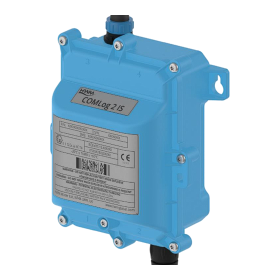
Quick Start Guide: COMLog 2 IS
Warning:
Always read this manual in conjunction with the Safety Supplement
which contains important safety and operating information.
Please read, understand and follow the instructions in the manuals.
Additionally, carefully read and follow the information in the
"Safety Warnings and Approvals Information" document.
Installation (Using HWM IDT).
(Automatic Meter Reading models).
1
MAN-157-0005-A
November 2020
Advertisement
Table of Contents

Subscribe to Our Youtube Channel
Related Manuals for HWM COMLog 2 IS

Summary of Contents for HWM COMLog 2 IS
- Page 1 Quick Start Guide: COMLog 2 IS Installation (Using HWM IDT). (Automatic Meter Reading models). Warning: Always read this manual in conjunction with the Safety Supplement which contains important safety and operating information. Please read, understand and follow the instructions in the manuals.
-
Page 2: Table Of Contents
Note(s): 1. Loggers will be set to call in with meter reading data and other messages to a server. This could be one of the HWM central servers or to your company’s own server (with HWM logger communication software installed). -
Page 3: Prepare
REPARE 1. Install required apps Install “IDT” onto ✓ a mobile phone Links: IDT: Google Play and the Google Play logo are trademarks of Google LLC. 2. Configure IDT app and Login Launch IDT. (When IDT used with DataGate login): Contact your supervisor or administrator for the Server URL, your username and your password. -
Page 4: Choose Logger Model
HOOSE OGGER ODEL Several logger types are available. Examine the meter at the installation site and choose the correct logger model (and adaptor cables) for the job. Common Models and examples of use: (Note: ‘ ’ indicates unspecified option) HIS/F0K0Q/*/*/C - Flow (Uni directional, 1 channel) + Tamper alarm option. -
Page 5: Installation
NSTALLATION 1. Un-pack logger Dispose of packaging responsibly. 2. Install logger. This product is only to be installed and connected by a fully ATEX trained installer. Check on available space in the meter cabinet and decide where to position the logger, antenna, and cables. -
Page 6: Activate Logger / Wireless Communications
CTIVATE OGGER IRELESS OMMUNICATIONS Logger must be activated during installation. Hold a strong magnet in the position shown. Wait 12s, then remove the magnet. If logger Bluetooth-compatible communications • is in standby, it becomes active. Logger communications stays active for 120s, •... - Page 7 2. Setup Logger ID and time-zone “Configure Device”. “Device Information”. Set local time-zone. 3. Display existing Channel settings (summary) The required logger settings will vary according to the meter and other equipment used at the site. Tap the Channels icon. (A “Combo”...
- Page 8 4 Check / Edit logger Flow Channel 1 settings Tap the Flow channel line to show its details. This screen is to set the volume measurement characteristics of the logger to match the meter’s pulse outputs. Note: These details can normally found within the data-sheet for the meter, but typically are found on the meter or pulse-head, as shown below.
- Page 9 5 Check / Edit logger Flow Channel 1 Pulse Sample rate and Pulse replication settings Tap on the “Advanced” tab. Check the channel settings… The “Global pulse sample rate” should be set to • “Low Power” for most meters, for best battery life. (Pulse width minimum 500ms, 50% duty cycle).
- Page 10 Tap on “Tamper Alarm Combo” to set up the tamper alarm. (This activates IDT to make several changes to logger settings in order to produce a Tamper Alarm). The tamper alarm settings are shown below (a) and (b): A new channel is created measuring the open-circuit time of input Status2 (/ Flow2).
-
Page 11: Set Meter Reading Of Flow Channels
The channels summary shows the presence of the newly added channel and a combo being set to trigger in the new channel. A summary of the tamper alarm combo is shown opposite and can be used to check if the combo has already been set. - Page 12 Read the main meter, noting its format. Enter the meter reading into the “Initial reading” field. When entering the meter reading, include any leading zeros, the decimal point and any other displayed digits. For the example shown, enter “020339 . 82”. Tap the back-arrow and the entered reading for Meter 1 is now shown.
-
Page 13: Add Any Additional Combos
Set your DataGate destination Set network details for your SIM provider. Note: These settings can (as an option) be pre-configured by HWM to customer requirements. 2. Call Test. Check in final position with door of meter cabinet (or lid on chamber) closed. -
Page 14: Complete Installation
• (Where the meter cabinet is constructed of metal, it may be required to cut a hole and fit a button-type antenna). – Contact HWM for antenna options. Repeat the call test when optimal antenna position is found. OMPLETE INSTALLATION 1. - Page 15 4. Logger calls in with measurement data (when used with DataGate). Logger contacts server at call-in time, and uploads measurement data. Logger can call server (or other server) immediately if an alarm condition is detected and the combo settings require it.
- Page 16 All images, text and designs are protected by international and UK copywrite law and remain the property of HWM-Water. It is against the law to copy or use any of the content from the HWM website or literature without the written consent of HWM-Water.
Need help?
Do you have a question about the COMLog 2 IS and is the answer not in the manual?
Questions and answers