Advertisement
Quick Links
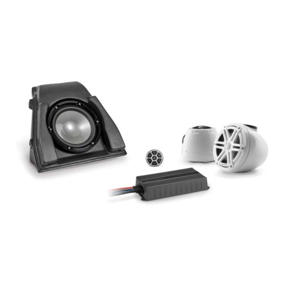
SlamPak
I N S T A L L A T I O N G U I D E
for the
SLPK-YA-19FXC
SKU# 94670 & 94671
&
SLPK-YA-19FXC-SUB
SKU# 94674
2019-Up Yamaha FX
™
SLPK-YA-19FXC / SLPK-YA-19FXC-SUB INSTR_SKU# 011531
If you choose to perform the installation yourself, it is absolutely
vital that the SlamPak™ be properly mounted to the vessel
according to these instructions. Failure to mount the enclosures
properly presents two problems:
1) A loose enclosure presents a serious safety hazard in the event of a
collision, rollover, or sudden deceleration.
2) The sub-bass performance will suffer due to the movement of the
enclosure caused by the force exerted by the woofer(s).
Thank you for choosing a JL Audio SlamPak™ for your marine sound system.
With proper installation, your new marine audio sound system
will deliver years of listening pleasure.
We strongly recommend that you have your new SlamPak™ installed by your
authorized JL Audio dealer. The installation professionals employed by your
dealer have the necessary tools and experience to disassemble and reassemble
your vessel properly. If you prefer to perform your own installation, please read
this installation guide completely before beginning the process.
INSTALLATION
DIFFICULTY:
5
5
OUT
OF
ESTIMATED TIME:
3-4 HOURS
Continued on Next Page
Advertisement

Related Manuals for JL Audio SlamPak SLPK-YA-19FXC


Summary of Contents for JL Audio SlamPak SLPK-YA-19FXC
- Page 1 SlamPak ™ Thank you for choosing a JL Audio SlamPak™ for your marine sound system. With proper installation, your new marine audio sound system I N S T A L L A T I O N G U I D E will deliver years of listening pleasure.
- Page 2 1/4” Stainless Steel 1/4” Stainless Steel 1-4 - 20 Stainless Steel Hex Cap Screw (x8) Flat Washer (x10) Oversized Flat Washer (x6) Nylon Insert Locknut (x8) 11” Cable Ties (x10) Page 2 • JL Audio, Inc., 2020 Continued on Next Page...
- Page 3 Pan Head Screw (x4) 5/16 - 18 x 1” Stainless Steel 5/16” Stainless Steel 5/16” Stainless Steel Hex Head Bolt (x4) Split Lock Washer (x4) Flat Washer (x4) Loctite® Threadlocker (x1) Page 3 • JL Audio, Inc., 2020 Continued on Next Page...
- Page 4 Remove the three indicated screws from the carefully unclip and remove the storage accent panel on the port side, then remove the compartment lid. nut from the inside of the hull. Page 4 • JL Audio, Inc., 2020 Continued on Next Page...
- Page 5 S T E P 16 Remove the two bolts from under the upper Remove the four screws from around the access panel, and remove the panel from the steering column cover panel. vessel. Page 5 • JL Audio, Inc., 2020 Continued on Next Page...
- Page 6 S T E P 2 4 From under the console, unplug the main Enlarge the forward hole using a 1/4” drill bit. harness and the Menu Scroll / Alarm Mute switch. Page 6 • JL Audio, Inc., 2020 Continued on Next Page...
- Page 7 Slide a 1/4 - 20 x 1” Hex Cap Screw through the With the rivet removed, enlarge the hole in the lower mounting hole on the Amplifier Bracket, induction box mounting tab and the hull to into the hull. 1/4”. Page 7 • JL Audio, Inc., 2020 Continued on Next Page...
- Page 8 Bracket to the vessel using a 1/4” Oversized firewall. Flat Washer and a 1/4 - 20 Nylon Insert Locknut over each 1/4 - 20 x 1” Hex Cap Screw, and fully tighten. Page 8 • JL Audio, Inc., 2020 Continued on Next Page...
- Page 9 Cable Ties. Connect the positive power cable to one side of the Circuit Breaker and the 8 AWG Power Cable Extension to the other side. Page 9 • JL Audio, Inc., 2020 Continued on Next Page...
- Page 10 Head Screws, and reinstall the Latch Bracket, factory inserts, and hand tighten. ensuring the center tab is oriented downward. Secure the Latch Bracket to the subwoofer enclosure, and fully tighten. Page 10 • JL Audio, Inc., 2020 Continued on Next Page...
- Page 11 From the underside, add the thin round gasket, then secure the MBT-CRXv2 using the threaded fastening collar. Reference the illustration in the MBT-CRXv2 owner’s manual for details. Page 11 • JL Audio, Inc., 2020 Continued on Next Page...
- Page 12 Port VEX Adaptor oriented to the rear. Apply Loctite® Threadlocker to a pair of M6 - 1 x 20mm Socket Cap Screws, secure the Port VEX Adaptor to the VEX Speaker Enclosure, and fully tighten. Page 12 • JL Audio, Inc., 2020 Continued on Next Page...
- Page 13 Reinstall the accent panel on the port side. Reinstall the handle bar to the factory torque specification. Reinstall the throttle control and steering column cover panel, then reinstall the lower and upper handle bar cover panels. Page 13 • JL Audio, Inc., 2020 Continued on Next Page...
-
Page 14: Power Outlet
. j l a u d i o . c o m All specifications are subject to change without notice. “JL Audio®” and “How we play®” are registered trademarks of JL Audio, Inc. “Ahead of the Curve” and its respective logo are trademarks of JL Audio, Inc.
Need help?
Do you have a question about the SlamPak SLPK-YA-19FXC and is the answer not in the manual?
Questions and answers