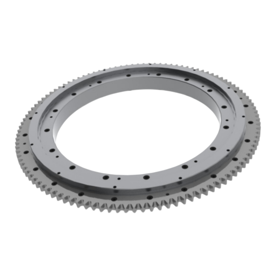
Summary of Contents for Nexen RPG-B
- Page 1 Precision Motion Control User Manual RPG-B, Rotary Drive System With Bearing FORM NO. L-21274-A-0113 SIT S.A. | Tfn. 943 457200 atencioncliente@sitsa.es | www.sitsa.es...
- Page 2 In accordance with Nexen’s established policy of constant product improvement, the specifications contained in this manual are subject to change without notice. Technical data listed in this manual are based on the latest information available at the time of printing and are also subject to change without notice.
-
Page 3: Table Of Contents
Table of Contents General Safety Precautions --------------------------------------------------------------------------------------------------- 4 System Design Overview: General System Requirements ----------------------------------------------------------------------------------------- 5 Mounting Requirements ---------------------------------------------------------------------------------------------------- 5 Pinion Requirements -------------------------------------------------------------------------------------------------------- 5 Proper System Alignment -------------------------------------------------------------------------------------------------------6 Mounting Surface Details --------------------------------------------------------------------------------------------------------6 Installation: System Mounting ------------------------------------------------------------------------------------------------------------- 6 Dial Plate Mounting (Output) --------------------------------------------------------------------------------------------- 6 Roller Pinion Installation: Shaft Mounted Pinion Installation ---------------------------------------------------------------------------------------7 Flange Mount Pinion Installation (ISO 9409) ----------------------------------------------------------------------8... -
Page 4: General Safety Precautions
WARNING Ensure proper guarding of the product is Failure to properly support the load used. Nexen recommends the machine before disengaging the RPG system builder design guarding in compliance with could cause serious harm to operators or OSHA 29 CFR 1910 “Occupational Safety equipment. -
Page 5: System Design Overview
Another possible preloading method utilizes a bracket with an eccentric mounting slot pattern. Nexen offers a preloading mechanism that is easy to integrate into your application as shown in Figure 11. Spring loaded preloading mechanisms should not be used since the spring force required to counteract the separation forces are much higher than the allowed preloading force and would cause a reduction in pinion needle bearing life, and increase system noise. -
Page 6: Proper System Alignment
MOUNTING SURFACE DETAILS Rotation .02 mm A The surface used to mount the RPG-B should be machined Tolerances Allowed In Roller Pinion Setup to a flatness of .050mm as shown to ensure proper Additional dimensional detail can be found in Nexen’s alignment. -
Page 7: Roller Pinion Installation
ROLLER PINION INSTALLATION Note: There are two pinion mounting styles, shaft or flange Ti g h t e n i n g O r d e r mount. Refer to the following section that applies to In n e r B u s h i n g H a l f O u t e r B u s h i n g H a l f your situation. -
Page 8: Flange Mount Pinion Installation (Iso 9409)
10. Once the fasteners are fully torqued verify the pinion is centered on the gear. If not, measure the positional error and then remove the pinion as described in the Disengaging The Roller Pinion section on page 12. Repeat the pinion installation procedure and offset the pinion by the recorded error plus the previous off set value. - Page 9 13. Clean the pinion flange and pilot where it will contact the adapter (if used) or gearhead flange inspecting for contaminates, burrs, or surface defects that would interfere with full contact between the pinion and adapter (if used) or gearhead flange. 14.
-
Page 10: Applying Preload
0.010 - 0.015 mm away from the gear teeth. For the Nexen Preloader [0.0004 - 0.0006 in] beyond first contact with teeth. -
Page 11: System Alignment Verification
40 [350] and then tighten the preload lockdown bolts to RPS-PRE-140 M8x1.25 40 [350] their recommended torques. See T able 4 for Nexen RPS-PRE-200 M12x1.75 120 [1060] Preloader System torque values. Typically the preload will change slightly when the preloader lockdown bolts Gearhead Screws (Mtg. -
Page 12: Disengaging The Roller Pinion
Nexen recommends lubricating the gear teeth every 2 following Kinematic Viscosity Levels: CST@40C = 25; million pinion revolutions or 6 months, but it may need to CST@100C = 5. -
Page 13: Warranty
Buyer shall be obligated to pay or which Buyer may incur based upon, related to or arising out of its contracts with its customers or other third parties. In no event shall Nexen be liable for any amount of damages in excess of amounts paid by Buyer for Products or services as to which a breach of contract has been determined to exist.


Need help?
Do you have a question about the RPG-B and is the answer not in the manual?
Questions and answers