
Related Manuals for GreenWorks GST80321


Summary of Contents for GreenWorks GST80321
- Page 1 80V Brushless String Trimmer GST80321 Owner’s Manual TOLL-FREE HELPLINE: 1-855-345-3934 www.GreenWorksTools.com Read all safety rules and instructions carefully before operating this tool.
-
Page 2: Table Of Contents
CONTENTS Introduction .......................... 2 Important Safety Instructions ....................3 Symbols ..........................6 Know Your String Trimmer ....................8 Assembly ..........................9 Operation ........................... 12 Maintenance..........................17 Troubleshooting........................18 Warranty........................19 Exploded View and Part List ....................20 PRODUCT SPECIf ICATIONS 80V BRUSHLESS STRINg TRI mmER Type ..................... -
Page 3: Important Safety Instructions
IMPORTANT SAf ETY INSTRUCTIONS W A R N I N g Read and understand all instructions before using this product. f ailure to follow all instructions listed below may result in electric shock, fire, and/or serious personal injury. • Do not operate power tools in explosive atmospheres, such as in the presece of flammable liquids, gases, or dust. - Page 4 • Remove or disconnect battery before servicing, cleaning or removing material from the gardening appliance. • Use only Greenworks 80-volt batteries. • Store idle appliances - When not in use, string trimmer should be stored indoors in a dry, locked place out of the reach of children.
- Page 5 IMPORTANT SAf ETY INSTRUCTIONS • When not in use, string trimmer should be stored indoors in a dry, locked up place—out of the reach of children. • Maintain tool with care. Keep vents clean for best and safest performance. f ollow instructions for proper maintenance.
-
Page 6: Symbols
SYMBOLS Some of the following symbols may be used on this product. Please study them and learn their meaning. Proper interpretation of these symbols will allow you to operate the product better and safer. SYmBOL NAmE DESIgNATION/EXPLANATION Volts Voltage Amperes Current Hertz frequency (cycles per second) - Page 7 SYMBOLS The following signal words and meanings are intended to explain the levels of risk associated with this product. SYmBOL SIgNAL mEANINg DANgER Indicates an imminently hazardous situation, which, if not avoided, will result in death or serious injury. WARNINg Indicates a potentially hazardous situation, which, if not avoided, could result in death or serious injury.
-
Page 8: Know Your String Trimmer
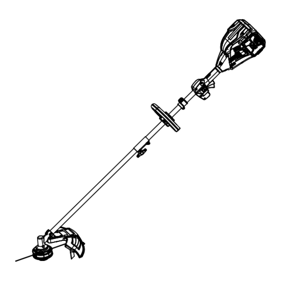
KNOW YOUR STRING TRIMMER KNOW YOUR STRINg TRImmER (See Figure 1.) The safe use of this product requires an understanding of the information on the product and in this operator’s manual as well as a knowledge of the project you are attempting. Before use of this product, familiarize yourself with all operating features and safety rules. -
Page 9: Assembly
ASSEMBLY UNPACKINg This product requires assembly. • Carefully remove the product and any accessories from the box. Make sure that all items listed in the packing list are included. • Inspect the tool carefully to make sure no breakage or damage occurred during shipping. •... - Page 10 ASSEMBLY ATTACHINg THE gUARD (See Figure 2.) NOTE: Install the guard before the attachment is connected to the power head. • Invert the string trimmer to access the trimmer head. • Using a Phillips head screwdriver (not included), remove the pre-installed screws from the trimmer head.
- Page 11 ASSEMBLY POSITIONINg HOLE RELEASE BUTTON ATTACHmENT KNOB ATTACHmENT SHAFT Fig. 3 NOTE: When using string trimmer attachments, use only .080 in. diameter line. The attachment connects to the power head by means of a coupler device. • Loosen the attachment knob on the coupler. •...
- Page 12 ASSEMBLY ADJUSTINg THE CUTTIN g SWATH (See Figure 5.) The trimmer is currently set at a 14 in. cutting swath. To adjust to a cutting swath of 16 in.: • Remove the battery from the string trimmer. • Remove both screws on the cut-off blade with a Phillips screwdriver (not included). •...
-
Page 13: Operation
OPERATION W A R N I N g Read and understand entire Operator's Manual for each optional attachment used on this power head and follow all warnings and instructions. failure to follow all instructions may result in electric shock, fire and/or serious personal injury. W A R N I N g Do not allow familiarity with this product to make you careless. - Page 14 OPERATION LOCK-OUT BUTTON (See Figure 7.) The lock-out button reduces the possibility of accidental starting. The lock-out button is located on the handle above the switch trigger. The lock-out button must be depressed before you pull the switch trigger. The lock resets each time the trigger is released. STARTINg AND STOPPIN g THE TRI mmER (See Figure 7.) To start: •...
- Page 15 OPERATION Fig. 8 W A R N I N g Any contact with the attachment cutting head can result in burns and/or other serious personal injury. W A R N I N g Extreme care must be taken when using a blade attachment to ensure safe operation. Read the safety information for safe operation when using a blade attachment and refer to the safety rules and instructions in your attachment manual.
- Page 16 OPERATION INSTALLINg STRIN g IN STRINg HEAD (See Figure 9.) Line up the slots on the spool cap with the slots on the string head. Spool Cap Insert line through the string head hole. Push line String Head until it exits the opposite string head hole. Pull the line through until there is an equal amount of line on each side.
- Page 17 OPERATION LINE TRImmINg CUT -OFF BLADE (See Figure 11.) The trimmer is equipped with a line trimming cut-off blade on the guard. Replace the string when trimming efficiency diminishes. This will maintain best performance. CUT-OFF BLADE Fig. 11 CUTTINg TIPS (See Figure 12.) •...
-
Page 18: Maintenance
MAINTENANCE W A R N I N g When servicing, use only identical replacement parts. Use of any other parts may create a hazard or cause product damage. W A R N I N g Before inspecting, cleaning, or servicing the machine, shut off motor, wait for all moving parts to stop, and disconnect extension cord. -
Page 19: Troubleshooting
TROUBLESHOOTING PROBLEm CAUSE SOLUTION Check the battery charge. Recharge the battery per the instructions in the battery manual. Check the power button. Push the power button if no Motor fails to start when switch LED's are illuminated. trigger is depressed. Battery is not secure. -
Page 20: Warranty
4 year consumer warranty, 1 year commercial warranty against defects in materials, parts or workmanship. GREENWORKS™, at its own discretion will repair or replace any and all parts found to be defective, through normal use, free of charge to the customer. This warranty is... - Page 21 EXPLODED VIEW...
- Page 22 PARTS LIST Item No. Part No. Description 31109719 Power head assembly 31111719 Auxiliary handle 34101185-4 Auxiliary handle base 33303719 Auxiliary handle screw 31110719 Lower shaft assembly 31105719 Guard assembly 34108178A Dual line spool assembly 3220905B Battery 31105719 Washer 34108178A Spacer 3220905B Charger...
- Page 23 TOLL-FREE HELPLINE: 1-855-345-3934 Rev: 00 (11-08-14) Printed in China on 100% Recycled Paper...
Need help?
Do you have a question about the GST80321 and is the answer not in the manual?
Questions and answers