Table of Contents
Advertisement
Advertisement
Table of Contents

Subscribe to Our Youtube Channel
Related Manuals for EFT Z Series


Summary of Contents for EFT Z Series
- Page 1 Z SERIES AGRICULTURAL DRONE SYSTEM (Model:Z30/Z50) User Manual Version1.0 EN...
-
Page 2: Table Of Contents
Contents Disclaimer ..........................2 Safety Guidelines ......................... 3 List of Items .......................... 5 Introduction ...........................6 Pre-flight Preparation ......................8 Inspection ........................8 Smart Battery ........................ 8 Remote Control Introduction ....................10 Overview ........................10 Function Introduction ....................11 Description of Status Indicator ..................11 Touchscreen Introduction .................... - Page 3 Sensor Calibration .......................25 Parameter Settings ......................27 Advanced Setting ......................30 Map Type ........................30 Pre-flight Test ........................30 Unlock/Landing ......................30 Motors Test ........................31 Nozzle Test ........................31 Spraying Operation Modes ....................31 Operation Mode Switch ....................31 Manual Operation Mode ....................32 Auto Operation Mode ....................
- Page 4 Assembly Guide For installation, please refer to the Manual. If you have not Z Series Assembly Instruction received it, please contact EFT official customer service to get it. Videos For detailed tutorial videos, please follow EFT Official Media Channel. Website:...
-
Page 5: Disclaimer
7. On any account, you shall comply with the laws and regulations of the country and the region where the product is used. EFT shall assume no liability arising from your violation of relevant laws and regulations. 8. To the extent permitted by law, EFT reserves the rights for final explanation and revision of the... -
Page 6: Safety Guidelines
EFT also has the right to update, modify or terminate these terms and conditions via channels including its official website, the User Manual and online App, without prior notice. Safety Guidelines If you are a beginner ,it is recommended to finish the training courses ,or get assistance ... - Page 7 Speed limit≤15m/s, distance limit≤1000m, it is recommended that the flight height be 2.5m~3.5m from the top of the plant, please operate correctly within the safety limit. MOS smart battery is required. Keep the product away from heat to prevent damage to the electronic component and ...
-
Page 8: List Of Items
List of Items Please check that all of the following items are present when unpacking the boxes. Packaging form:CKD Number of packages:2 cartons Items as below : CW motor x2 Arms x4 Drone body x1 Spray tank kit x1 CCW motor x2 CW Paddle x2 Centrifugal nozzle x2 Rear crossbar x1... - Page 9 Three solutions are optional, as follows: Item Basic set Advanced set Standard set Drone frame √ √ √ Motor set*4 √ √ √ Impeller pump*2 √ √ √ Flowmeter √ √ √ Liquid level gauge √ √ √ Centrifugal nozzle*2 √...
-
Page 10: Introduction
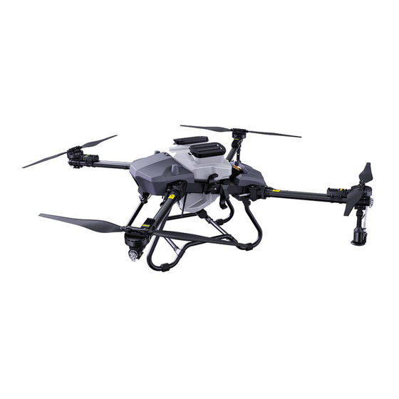
Introduction Aircraft Features The Z series agricultural UAV system solution is a full configuration solution provided by EFT. It has two load models of 30kg and 50kg and is delivered in a semi-assembled form. It adopts truss structure and Z-shaped folding arms to minimize the folding volume and facilitate transportation. -
Page 11: Pre-Flight Preparation
①Motor set ⑮Flight control ⑧Camera ⑨Rear cover ②Arm(Φ50mm) ⑯Receiver ③Landing gear ⑩Landing gear crossbar ⑰Level gauge ④Spraying tank ⑪Arm buckle ⑱Impeller pump ⑤Centrifugal nozzle ⑲Ultrasonic flow meter ⑫Radar ⑥Cabin ⑬Antenna ⑦Front cover ⑭RTK Pre-flight Preparation Inspection Check whether the components are in good condition, especially the landing gear , the ... - Page 12 the clasp. Warning Before installing the battery, please keep the interfaces at both ends clean, dry, no metal debris and liquid residue. Before starting the battery, please ensure that the battery is fully inserted to avoid flight accidents during operation due to the battery not being tightly connected. Make sure the battery power is off before inserting or removing the battery.
-
Page 13: Remote Control Introduction
Remote Control Introduction Overview Antenna AB Dot Lever Mode Switching Lever RC Status Indicator Battery Level Indicator Power Button Control Sticks Undefined Switch Operation Button 5.5inch LCD Touch Screen Upgrade Speaker Type-C 1/4inch Screw Hole... -
Page 14: Function Introduction
Right Dail Left Dail HDMI Function Introduction Left Dial: Undefined, can be customized. ① Top Left Lever: The flight mode switch of controlling aircraft (Attitude mode, Manual mode, ② Work mode). Top Right Lever : In the AB mode, dot A point in the middle and turn up to dot B. ③... -
Page 15: Touchscreen Introduction
Solid red light: Not communicating with aircraft ⑨ Flashing yellow and red light : Level 1 alarm of remote control temperature ⑩ Flashing yellow and twice red light : Level 2 alarm of remote control temperature Flashing yellow and triple red light : Level 3 alarm of remote control temperature Flashing green and red light : Level 1 alarm of receiver temperature ⑪... -
Page 16: Power On/Off Remote
② Solid red light of the indicator, it is charging. ③ Solid green light of indicator, it is fully charged. Power On/Off Remote The steps as below: ① Turn on : Short press the once, then press and hold until a beep sound. ②... -
Page 17: Connection And Settings
The following description of the American Hand mode: Aircraft Remote Controller (Indicates nose Remarks direction) Throttle Stick: Move the left stick vertically to control the elevation of the aircraft. Left Stick Push up to ascend and push down to descend. Use the left stick to take off when the motors are spinning at an idle speed. - Page 18 2. Click System. 3. Click“Start”and set as below. 4. Press LINK button for 2s, flash green quickly to indicate that it is linking until turn to slow flashing, the linking is completed.
-
Page 19: Remote Control Setup
LINK Button Remote Control Setup Channel Enter SIYI App, you can customize the channel settings. It is recommended to set channel 6 as SB gear lever, channel 7 to A, channel 8 to B, channel 9 to C, channel 10 to D, and channel 15 to A. - Page 20 Datalink Enter Datalink Setting, Device ID is automatic identification. Set the Connection to "UART", the...
-
Page 21: Agri Assistant App
Flight Controller to "JIYI(K3-A)", and the Baud Rate to "57600". Then the remote setting is complete. Agri Assistant App Home Screen ② ③ ① ⑥ ④ ⑤ ① Connect:Click to connect to the aircraft. ② Ground Plan:Click to add plot. ③... -
Page 22: Account Registration And Activation
⑥ My:View user information. Account Registration and Activation 1. Register Open the latest Agri Assistant APP, click “Register”. If you have the manufacturer account, you can directly enter the password to log in, and click “Connect”. If the connection fails, you can directly click Start>... - Page 23 3. Plan Add After the verification is successful, click Device Manager > Plan Add, the Drone ID will be automatically identified, the Drone Name, Drone Type, and Drone Number can be customized , and fill in your direct supplier company to Manufacturers. 4.
- Page 24 *Read First ,Then Verify 5. Ntrip Setting...
-
Page 25: Operation View
If you purchased RTK and is used outside of China, please click Device Manager >Tool Management >Ntrip Settings, and apply for an Ntrip account to log in. For the application method, please contact the local RTK Service provider. 6. Connect Aircraft Back Home, Click “Connect”>Start (choose H12/MK15) to enter the operation interface. -
Page 26: Debugging Before Takeoff
② Switching between AB Route Operation Mode and Auto Operation Mode ③ Return to the Home Point Slide the icon to the specified position according to the interface instructions. ④ FPV Camera View Display the live view from the FPV camera. Tap to switch between the Map View and Camera View. -
Page 28: Gate Set
Gate Set Channel Settings can be read directly from default settings CH 6 as AB, CH8 as Avoid, CH9 as Pump, CH10 as Engine. It can also be customized based on local operation habits. Then “Save” and the RC mode set as “American hand”. Sensor Calibration All new drones should do Accelerometer calibration and Compass calibration. - Page 29 Compass calibration Click “Compass calibration”, check the instructions on the screen, when it indicates “doing x, the level of uniform rotation”, lift the aircraft up and rotate it horizontally until it indicates “doing z, the nose down uniform rotation”, then press the instruction to point the drone head down and continue to rotate until it indicates “Compass calibration normal”, then put down the aircraft.
-
Page 30: Parameter Settings
④ Click on the flow meter to calibrate, stop it before finishing the water spray; ⑤ Measure the weight of each pail one by one, subtract the net weight of the pail, and input the amount to channel 1 and channel 2 respectively (Facing the tail, channel 1 on the left and channel 2 on the right), then click OK. - Page 31 Enter Agri Assistant > Start > > >Spay. It is recommended to set Liq protection to Back, Liquid Type to Flow meter, Level Type to Switch. If the liquid level gauge going wrong, it can be adjusted to the flow meter mode. Select the Work mode accordingly and save it. 2.
- Page 32 positioning. The EXT2 Type in K-Box set as “K-BOX4”. Dot Device, Seed Manager, Arm alarm etc. can be set according to needs.
-
Page 33: Advanced Setting
Advanced Setting The advanced settings are generally defaulted by the factory, and the settings can be directly read and save. Please keep default settings. If the flight is unstable, you can contact the after-sales service to get the guidance. Map Type Enter Agri Assistant >... -
Page 34: Motors Test
(left stick in American Hand) Note Stay away from spinning propellers. Do not start the motors in narrow space or where there are people nearby. Keep controlling of the remote controller during the motors work. Do not stop the ... -
Page 35: Manual Operation Mode
② Manual:Keep the left lever in the middle. ③ Attitude:Move the left lever to the rear position. ④ AB:The middle position of the right lever is point A, and the front position is point B. (*With RTK, the aircraft can hover precisely, achieve centimeter-level positioning. Without RTK, the aircraft is positioned by GPS) Manual Operation Mode 1. -
Page 36: Auto Operation Mode
Auto Operation Mode A-B Route Operation Two methods can enter the AB operation mode: Method 1: 1. Click Agri Assistant >Connect > H12/MK15 >Start 2. Complete the preflight inspection and unlock for takeoff in Attitude Mode. 3. After takeoff, fly to the field where you want to work. After the aircraft stabilizes, click “A”to enter the AB operation mode. -
Page 38: Fully Auto Operation
Method 2: Fly to the field where you want to work. After the aircraft stabilizes, move the left lever on the side close to you. Switch Attitude to Auto mode, and then fly to the A position to add point A , the detailed flight parameters will appear on the screen. - Page 39 2. Select the planning method①Handheld GPS(RTK point device) ②Flight GPS ③Map Selection ④Waypoint planning. Method① and ② are widely used.
- Page 40 3. Set Ground Name, move the handheld point device or fly the aircraft to the field, click the Boundary Point on the right side of screen to add dots in turn. 4. About obstacles, move handheld point device or fly the aircraft to the obstacles, click Obstacle Point.
- Page 41 Click “Save” after all operations are done, tap on the left, select the newly saved plot, click Share > Confirm, the plot information is listed in Block Data.
-
Page 42: Switch Spreading System
Click Confirm and Slide Right Start to take off. Switch Spreading System *Note: The spreading system is optional. Please refer to the Z Series Assembly Instruction Manual for installation. Spreading System Debugging 1. Sowing mode, click Start> >... - Page 43 2. Weight Calibration. Click > >Seed Manager> Peeling Calibration, wait 3s, check the display of the remote control, if weight is 0, peeling calibration is finished. Then Click “Weight Calibration”, pour objects (over 10kg) into the tank, enter the measured weight , click “Save” and wait 3s, check the weight display, if it is the same as the known weight (The error range is 0.02kg), calibration is done.
- Page 44 3. Click “Spread” in the top bar, set Sowing mode to “Precision sowing”, Template Selection to “Create”, enter the object name, set the parameters, such as the Hec Dosage, Disc speed, Flying speed, etc., then “Save”.
- Page 45 4. Enter “Spread” again, select the newly created template, remove the spreader turntable. Add at least 15KG object, click “Flow calibration” to complete the spreading debugging.
-
Page 46: Spreading Operation
Spreading Operation 1. Open the Agri Assistant App, select Ground Plan >New Plot>Map Selection>Set Ground Name, circle the plots , then “Share”. 2. Click , select the plots, set Hec Dosage, Disc speed, Flying speed and other parameters, Click Confirm and Slide Right Start to take off. -
Page 47: Maintenance
Maintenance Cleaning After Operation Clean the device timely after each operation to prolong life-span. Follow the cleaning steps: Detergent: soapy water or laundry powder. ①Fill the tank with soapy water or the laundry powder. Start spraying to clean pesticide residues in the spraying system. - Page 48 Regular maintenance ensures that the device performs at its best in future operations with fewer malfunctions and improved efficiency. Maintenance steps are as follows: Drone frame ①Check if any screw on the frame is loosening or missing. ②Check if the components including landing gears, fuselage, arms, motors and antennas are in good condition.
-
Page 49: Transportation
5%) due to chemical corrosion, thick pesticides, replacement of peristaltic pump parts, etc. Calibration needs to be done with clean water or pesticides used in operation. In case the health index remains unusual after calibration, check whether the peristaltic pump tubes or spray tubes are in good condition. -
Page 50: Supplements
Note Before transporting, clean and empty the spraying system and drain all tubes to avoid damage to other devices during transportation. Pesticide packaging and sewage must be collected for proper disposal to avoid hazards. Never place batteries in the aircraft for transportation. ... -
Page 51: Log Drownload
Log Download 1. Open Agri Assistant >Device Manager>Tool Management>Log Download, select the log to be downloaded. Click "share", recommend to share to the Files, return to the Home screen, in the multitasking center, find the logs shared , you can link the remote control via bluetooth or data cable to share to other devices. -
Page 52: Alarm
Alarm There are two methods to get alarm information: Method 1: Open Agri Assistant, click My>Alarm Message, check the prompts during operation from the Alarm List, you can modify it according to the suggestions. -
Page 53: Appendix
Method 2: When the aircraft has connected, select Agri Assistant >Start, click the device management bar in the upper left corner, get alarm prompt information in Sensor Status. Appendix Specifications Item Parameter Unloaded Spraying drone 29.8kg 31.5kg weight (without batteries) Unloaded Spraying drone weight 40kg... - Page 54 2435*2541*774mm 2845*2718*890mm Spraying drone: Spraying drone: 979*684*752mm 1066*677*830mm Folded size Spreading drone : Spreading drone:1066*677*890mm 979*684*774mm 17.5min 20min ( Test by14S 30000mah ) ( Test by18S 30000mah ) No-load hovering time 7.5min 7min (Test by 14S 30000mah) (Test by18S 30000mah) Full load hovering time Working temperature 0-40℃...
- Page 55 Operating Voltage 12-80V Working temperature -10~60℃ Flight Level±0.1m,Vertical ±0.1m control Level±1.5m , Vertical±0.5m Sustained wind : level 4, Gust : level 5 Wind resistance level Resolution 1080*1920 display screen 5.5inch Working time Remote 5h ( 20W ) control Charging time 3km(3mHeight without shelter)...
Need help?
Do you have a question about the Z Series and is the answer not in the manual?
Questions and answers