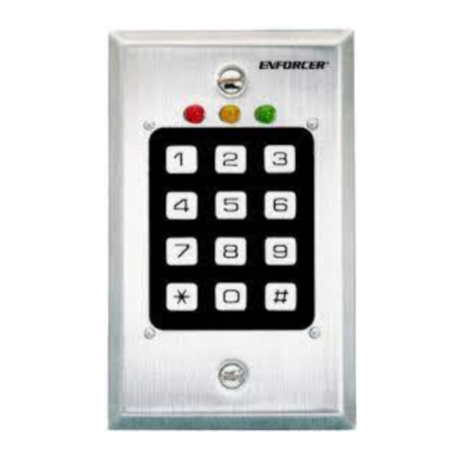
ENFORCER SK-983A, SK-983A100 - Digital Access Keypad Manual
- Installation manual (2 pages)
Advertisement
INTRODUCTION
The SK-983A is the ideal keypad for office and home security installations. It is a self-contained security keypad with a built-in 5A relay for electric door strike and other security and access control applications. With its EEPROM memory, the keypad s programmed data is saved in case of power failure. Security is assured with over 100 million possible combinations for the master, user, duress, and quick codes. Other security features include duress output and a built-in tamper switch. For convenience, the SK-983A also supports egress input (a push-button switch inside the protected area for easy exit when oneway security is sufficient).
TERMINALS

- 12VDC IN - Connect to the (+) and (-) terminals of a 12VDC power supply. The keypad s (-) terminal is the grounding point for the keypad. Important Connect to a regulated power supply only.
- DU OUT (Duress Output) - Outputs a transistor ground when the Duress Code is entered. Connect to activate an alarm control panel or telephone dialer. Output: Ground (-) output, 100mA, 25VDC max.
- EG IN (Egress Input) - Connect to the 12VDC IN (-) terminal via a momentary push-button switch. Allows user to bypass the security code by pushing the push-button switch. This switch is normally put inside the protected premises near the door to allow those inside the protected premises to exit without keying in the code. Leave this terminal open if it is not used.
- O/P RELAY - 5A N.O. dry relay contact for connection to a door striker. Programmable N.O. or N.C.
![]()
Connect the included 1N4004 diode in parallel to the electric strike or magnetic lock. - N.C. TAMPER - N.C. contact when the keypad is secured on the back box. The contact opens when the keypad is separated from the box. Connect to the 24-hour zone of an alarm system if necessary.
VISIBLE AND AUDIBLE INDICATORS
- RED - Lights ON when the first digit of the entry code is pressed. Remains on for 10 seconds, during which time the entire code must be entered. If the entire code is not entered while the red LED is on, the entire code is canceled, and must be entered again from the first digit.
- AMBER - Program status indicator. Synchronized with the built-in buzzer s tone.
- GREEN - Lights ON when the 5A relay makes contact.
The built-in buzzer and the amber LED generate tones and signals to indicate programming status as shown in chart below.
| Amber LED output tones | Buzzer | STATUS |
| ON | none | In programming mode |
| 1 flash | 1 beep | Successful key entry |
| 2 flashes | 2 beeps | Successful code entry |
| 5 flashes | 5 beeps | Unsuccessful code entry |
| Continuous flash | Continuous beeps | DAP jumper not replaced |
| 1 flash every 2 seconds | none | Standby mode |
PROGRAMMING THE RELAY
The 5A relay can be programmed for N.O. operation via the on-board wire jumper. See figure below.

Programming the SK-983A Keypad
| Access Keys | Entry | Validation | Comments |
| First-time use -- Set the Personal Master Code | |||
| -- | Master Code (factory pre-set at 0000) | * | Enter the programming mode by keying in the Master Code |
| Programming -- Changing Master and User Codes | |||
| 0 | From 1 to 8 digits | # | Sets the 1 to 8 digit personal Master Code |
| 1 | From 1 to 8 digits | # | Sets the 1 to 8 digit User Code |
| Programming -- Configuration of relay output | |||
| 40 | Relay activate time to 999 seconds) | # | Relay has momentary output of 1 to 999 (from 1 seconds each time the User Code is inputted |
| 41 | -- | # | Relay latches ON or OFF each time the User Code is inputted |
| 42 | -- | # | Relay latches ON each time the Quick Code is inputted |
| Programming -- Personal safety | |||
| 70 | -- | # | After 10 successive incorrect code attempts, keypad locks out code for 30 seconds |
| 71 | -- | # | After 10 successive incorrect code attempts, keypad outputs Duress signal |
| 72 | -- | # | Neither of the above |
| Exit programming mode | |||
| -- | -- | * | Exits programming mode, returns to normal operation |
PROGRAMMING THE KEYPAD
To program the SK-983A, you will first need to decide the following information:
- The Master Code and/or the User Code.
- Relay configuration momentary or shunt, and relay momentary output time (1 to 999 seconds) in momentary mode.
- Whether or not Quick Code is to be used.
- Result of improper code entry after 10 successive tries (30-second code lockout, Duress output, or neither). Now you can program the keypad.
PROGRAMMING THE KEYPAD (EXAMPLE)
In this example, the following data will be stored in the keypad:
- Change the factory Master Code 0000 to a personal Master Code 3289.
- Set the User Code to 8321
- Set the relay output to momentary mode, 5 seconds.
- Set the keypad to lock 30 seconds after 10 consecutive incorrect code inputs.
Programming Enter the data as follows:
 | Enter the programming mode using the factory-set Master Code. |
 | 3289 has been stored as the new personal Master Code. |
 | 8321 has been stored as the new User Code. |
 | The relay output has been set to momentary mode with 5-second output. |
 | The keypad has been set to lockout code entry for 30 seconds following 10 consecutive incorrect code entries. |
 | Exit programming mode, with all desired data stored. |
Note: If you make a mistake, press the "#" to cancel, or wait 10 seconds, then re-enter.
FACTORY-SET DATA - IMPORTANT NOTE
For convenience in first-time programming, the SK-983A comes preprogrammed with the Master Code 0000. Additional codes and or data should be programmed at the owner s discretion. However, to ensure security, the owner should program a personal Master Code to replace the factory-set Master Code.
USING THE KEYPAD (EXAMPLES)
The following examples use the sample data programmed above.
Example 1 Activate the 5A relay with the User Code.
To activate the relay output (for instance, to energize the electric door striker), enter the User Code followed by the "#" key.
 | The relay output will be active for 5 seconds. |
Example 2 Activate the 5A relay with the Master Code.
Under normal circumstances, the User Code is used to activate the relay. However, if several keypads are programmed with the same personal Master Code but different User Codes, the relay can be activated by typing in the Master Code followed by" #1."
 | Relay output will be activated for 5 seconds. |
Example 3 Duress Code.
If a user is being forced by a thief to use the keypad to open a door, he/she can use the Duress Code. This allows a user under duress to activate the 5A relay and trigger an alarm at the same time. The keypad determines it automatically by adding 2 to the first digit of the User Code. (Example: If the User Code is 1234, then the Duress Code is 3234. If the User Code is 8321, then the Duress Code is 0321. ) To activate the Duress Output, enter the Duress Code followed by the # key.
 | The relay output will be active for 5 seconds, and a Duress signal is sent to an alarm control device. |
Example 4 Using the Quick Code
The Quick Code, if programmed, allows the keypad to latch the relay ON by keying the first 2 digits of the User Code. To turn the relay OFF, key in the entire User or Master Code. This is useful when, for instance, the relay needs to be ON during the day to allow unrestricted access to the protected premises, but OFF during the evening to restrict access. In this example, the supervisor uses the Quick Code to latch the relay ON in the morning, and the User Code to shut it off in the evening.
- To program the keypad for Quick Code:
 | The keypad is now in the programming mode, ready to receive new data. |
 | Set the relay to latch ON when the Quick Code is inputted. |
 | Exit the programming mode. |
- Now the relay will be latched ON when the first 2 digits of the User Code are inputted. The relay will be deactivated when the entire User Code is inputted:
 | Relay output is latched ON (activated). |
 | Relay output is latched OFF (deactivated). |
DAP JUMPER (SYSTEM RESET)
If the personal master code is forgotten, use the DAP jumper to override the forgotten code and permit direct entry into the programming mode as follows:
- Disconnect the power supply.
- Switch the DAP jumper from OFF to ON.
- Reconnect the power supply. The keypad will start beeping.
- Switch the DAP jumper back to the OFF position. The keypad will stop beeping.
- The keypad is now in the programming mode, ready to receive new data.
- Re-program the keypad as shown above, starting with the personal master code.
SPECIFICATIONS
Operation voltage — 12VDC (10~14VDC).
Current drain — 10-60mA.
Duress output — Transistor ground (-), 100mA, 25VDC max.
Codes available — Master, user, duress, and quick.
Code combinations — 111,111,100 possibilities.
Relay output — 5A, dry contact, programmable N.O. or N.C., 30VDC max.
Dimensions (keypad with back box) — 4 5/8" x 2 7/8 " x 1 7/8" (117 x 74 x 48 mm)
Weight (keypad with back box) .— approx. 6.2 oz (175g) net), 7.9 oz (225g) gross.
INSTALLATION DIAGRAM


- Leave unused terminals open.
- Connect the included diode 1N4004 across the electric latch.
- N.C. = Normally Closed
N.O. = Normally Open - Use a regulated power supply only. This will help prevent lockouts.
- The 1N4004 diode must be used to help prevent possible lockouts.
* This sample installation assumes the relay is programmed for N.O. operation.
WARRANTY
ENFORCER access keypads are warranted against defects in material and workmanship while used in normal service for a period of one (1) year from the date of sale to the original customer. Our obligation is limited to the repair or replacement of any defective part if the unit is returned, transportation pre-paid, to SECO-LARM.
SECO-LARM's policy is one of continual development and improvement. For this reason, SECO-LARM reserves the right to change specifications without notice.
Copyright ' 2003 SECO-LARM U.S.A., Inc. All rights reserved.
SECO-LARM U.S.A., Inc.
16842 Millikan Avenue, Irvine, CA 92606
Tel: 800-662-0800 / 949-261-2999
Fax: 949-261-7326
Website: www.seco-larm.com
E-mail: sales@seco-larm.com

Documents / Resources
References
Download manual
Here you can download full pdf version of manual, it may contain additional safety instructions, warranty information, FCC rules, etc.
Download ENFORCER SK-983A, SK-983A100 - Digital Access Keypad Manual
Advertisement


Need help?
Do you have a question about the SK-983A and is the answer not in the manual?
Questions and answers