
Subscribe to Our Youtube Channel
Related Manuals for Miller Hydracool 270


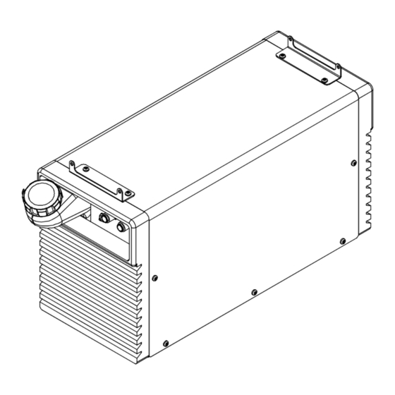
Summary of Contents for Miller Hydracool 270
- Page 1 All manuals and user guides at all-guides.com OM-266 361B 2015−06 Processes TIG (GTAW) Welding MIG (GMAW) Welding Description Hydracool 270 OWNER’S MANUAL Visit our website at www.MillerWelds.com...
- Page 2 All manuals and user guides at all-guides.com From Miller to You Thank you and congratulations on choosing Miller. Now you can get the job done and get it done right. We know you don’t have time to do it any other way.
-
Page 3: Table Of Contents
All manuals and user guides at all-guides.com TABLE OF CONTENTS SECTION 1 − SAFETY PRECAUTIONS - READ BEFORE USING ....... . . 1-1. - Page 4 Council Directive(s) and Standard(s). Product/Apparatus Identification: Product Stock Number HYDRACOOL 270 028042107 Council Directives: ·2006/95/EC Low Voltage ·2004/108/EC Electromagnetic Compatibility ·2011/65/EU Restriction of the use of certain hazardous substances in electrical and electronic equipment Standards: ·IEC 60974-1:2012 Arc Welding Equipment –...
-
Page 5: Section 1 − Safety Precautions - Read Before Using
All manuals and user guides at all-guides.com SECTION 1 − SAFETY PRECAUTIONS - READ BEFORE USING coolers 2013-10 Protect yourself and others from injury — read, follow, and save these important safety precautions and operating instructions. 1-1. Symbol Usage DANGER! − Indicates a hazardous situation which, if Indicates special instructions. -
Page 6: California Proposition 65 Warnings
All manuals and user guides at all-guides.com D Perform maintenance and service according to the Owner’s READ INSTRUCTIONS. Manuals, industry standards, and national, state, and local codes. D Read and understand the Safety Data Sheets (SDSs) and the D Read and follow all labels and the Owner’s manufacturer’s instructions for adhesives, coatings, cleaners, Manual carefully before installing, operating, or consumables, coolants, degreasers, fluxes, and metals. -
Page 7: Section 2 − Definitions
All manuals and user guides at all-guides.com SECTION 2 − DEFINITIONS 2-1. Additional Safety Symbols And Definitions Some symbols are found only on CE products. Warning! Watch Out! There are possible hazards as shown by the symbols. Safe1 2012−05 Do not discard product (where applicable) with general waste. Reuse or recycle Waste Electrical and Electronic Equipment (WEEE) by disposing at a designated collection facility. -
Page 8: Miscellaneous Symbols And Definitions
All manuals and user guides at all-guides.com Plugged filter or hoses can cause overheating to the power source and torch. Safe50 2012−05 100 h. Std. Every 100 hours, check and clean filter and check condition of hoses. Safe51 2012−05 2-2. Miscellaneous Symbols And Definitions Some symbols are found only on CE products. -
Page 9: Section 3 − Specifications
Coolant *HF: High Frequency Current ° ° **MILLER coolants protect to -37 F (-38 C) and resist algae growth. NOTICE − Use of any coolant other than those listed in the table voids the warranty on any parts that come in contact with the coolant (pump, radiator, etc.). -
Page 10: Section 4 − Installation
All manuals and user guides at all-guides.com B. Information On Electromagnetic Fields (EMF) This equipment shall not be used by the general public as the EMF limits for the general public might be exceeded during welding. This equipment is built in accordance with EN 60974−1 and is intended to be used only in an occupational environment (where the general public access is prohibited or regulated in such a way as to be similar to occupational use) by an expert or an instructed person. -
Page 11: Installing Unit On A Sth 270 Welding Power Source And Connecting 400 Vac Input Power
All manuals and user guides at all-guides.com 4-2. Installing Unit On A STH 270 Welding Power Source And Connecting 400 VAC Input Power Welding Power Source Have only qualified persons make this installation. Disconnect and lockout/tag- out input power before con- necting input conductors from unit. -
Page 12: Section 5 − Operation
All manuals and user guides at all-guides.com SECTION 5 − OPERATION 5-1. Control Panel Tank Filler Neck Supplementary Protector (CB1) Power On/Off Light Quick Connect; Water Out Quick Connect; Water In Power On/Off Switch Front Back 956172138_3-A Notes OM-266 361 Page 8... -
Page 13: Section 6 − Maintenance & Troubleshooting
All manuals and user guides at all-guides.com SECTION 6 − MAINTENANCE & TROUBLESHOOTING 6-1. Routine Maintenance Disconnect power before maintaining. n = Check Z = Change ~ = Clean l = Replace Reference * To be done by Factory Authorized Service Agent Every NOTICE −... -
Page 14: Flow Direction
All manuals and user guides at all-guides.com 6-3. Flow Direction Blue Outlet Flow Filter Inlet Flow Tank Radiator 956172140-A 6-4. Troubleshooting Trouble Remedy Coolant system does not work. Be sure cooler input power and communication cables from power source are connected to cooler receptacles. -
Page 15: Section 7 − Electrical Diagram
All manuals and user guides at all-guides.com SECTION 7 − ELECTRICAL DIAGRAM 956172139_A OM-266 361 Page 11... -
Page 16: Section 8 − Parts List
All manuals and user guides at all-guides.com SECTION 8 − PARTS LIST Hardware is common and not available unless listed. 26 27 956172138_5-A Figure 8-1. Main Assembly, Hydracool 270 CE OM-266 361 Page 12... - Page 17 Item Dia. Part Mkgs. Description Figure 8-1. Main Assembly, Hydracool 270 CE +116121128 Wrapper ..............
- Page 18 All manuals and user guides at all-guides.com Notes...
- Page 19 Effective January 1, 2015 (Equipment with a serial number preface of MF or newer) This limited warranty supersedes all previous Miller warranties and is exclusive with no other guarantees or warranties expressed or implied. LIMITED WARRANTY − Subject to the terms and conditions 90 Days —...
- Page 20 File a claim for loss or damage during Phone: 39 (0) 2982901 Fax: 39 (0) 298290-203 shipment. email: miller@itw−welding.it For assistance in filing or settling claims, contact your distributor and/or equipment manufacturer’s Transportation Department. © ORIGINAL INSTRUCTIONS − PRINTED IN USA 2015 Miller Electric Mfg. Co. 2015−01...
Need help?
Do you have a question about the Hydracool 270 and is the answer not in the manual?
Questions and answers