Table of Contents
Advertisement
Quick Links
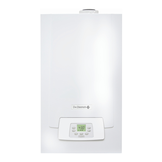
MPX 24 COMPACT
MPX 20/24 MI COMPACT
MPX 24/28 MI COMPACT
MPX 28/33 MI COMPACT
en
CONDENSING GAS WALL-HUNG BOILERS
pl
NAŚCIENNY GAZOWY KOCIOŁ KONDENSACYJNY
cs
PLYNOVÝ ZÁVĚSNÝ KONDENZAČNÍ KOTEL
sk
PLYNOVÝ ZÁVESNÝ KONDENZAČNÝ KOTOL
fr
CHAUDIERES MURALES A GAZ A CONDENSATION
Notice d'emploi et d'installation destinée à l'usager et à l'installateur
ro
CENTRALĂ TERMICĂ MURALĂ CU CONDENSARE, PE GAZ
Manual de instrucţiuni destinat utilizatorului şi instalatorului
el
ΕΠΙΤΟΙΧΙΟΣ ΛΕΒΗΤΑΣ ΑΕΡΙΟΥ ΣΥΜΠΥΚΝΩΣΗΣ
ru
НАСТЕННЫЙ ГАЗОВЫЙ КОНДЕНСАЦИОННЫЙ КОТЕЛ
Паспорт изделия. Руководство по установке и эксплуатации
A
Instructions manual for users and fitters
Instrukcja obsługi dla użytkowników i instalatorów
Návod na použití určený pro uživatele a instalatéra
Návod na použitie určený pre používateľa a inštalatéra
Εγχειρίδιο χρήσης για τον χρήστη και τον εγκαταστάτη
Advertisement
Table of Contents

Subscribe to Our Youtube Channel
Related Manuals for DeDietrich MPX 24 COMPACT


Summary of Contents for DeDietrich MPX 24 COMPACT
- Page 1 MPX 24 COMPACT MPX 20/24 MI COMPACT MPX 24/28 MI COMPACT MPX 28/33 MI COMPACT CONDENSING GAS WALL-HUNG BOILERS Instructions manual for users and fitters NAŚCIENNY GAZOWY KOCIOŁ KONDENSACYJNY Instrukcja obsługi dla użytkowników i instalatorów PLYNOVÝ ZÁVĚSNÝ KONDENZAČNÍ KOTEL Návod na použití určený pro uživatele a instalatéra PLYNOVÝ...
-
Page 2: Table Of Contents
Dear Customer, Our company is confident our new product will meet all your requirements. Buying one of our products guarantees all your expectations: good performance combined with simple and rational use. Please do not put this booklet away without reading it first: it contains useful information for the correct and efficient use of your product. -
Page 3: Description Of Symbols
DESCRIPTION OF SYMBOLS WARNING Risk of damage to, or malfunction of the appliance. Pay special attention to the warnings concerning danger to people. DANGER OF BURNS Wait for the appliance to cool down before working on the parts exposed to heat. DANGER - HIGH VOLTAGE Live components - electrocution hazard. -
Page 4: General Precautions
GENERAL PRECAUTIONS This boiler has been designed to heat water to a temperature lower than boiling point at atmospheric pressure. It must be connected to a central heating system and to a domestic hot water supply system according to its performance and power output. Before having the boiler installed by a qualified service engineer, make sure the following operations are performed: •... -
Page 5: Commissioning The Boiler
1. COMMISSIONING THE BOILER To light the boiler correctly, proceed as follows: • Check that the system pressure is correct (section 7); • Power the boiler; • Open the gas tap (yellow, positioned under the boiler); • Select the required heating mode (section 1.2). Key to BUTTONS DHW temperature adjustment (+ to increase the temperature and –... -
Page 6: Prolonged Shutdown. Anti-Freeze Protection
2. PROLONGED SHUTDOWN. ANTI-FREEZE PROTECTION Do not drain the whole system as filling up with water again could cause unnecessary and harmful scale to build up inside the boiler and the heating elements. If the boiler is not used during winter and is therefore exposed to the danger of frost, add some specific anti-freeze to the water in the system (e.g.: propylene glycol coupled with corrosion and scale inhibitors). -
Page 7: Boiler Information Menu
Delivery/return probe control test Call the Authorised Service Centre. Fan fault Call the Authorised Service Centre. Intervention of safety thermostat for excess temperature in Call the Authorised Service Centre. low temperature system Overheating exchanger Call the Authorised Service Centre. Call the Authorised Service Centre. Call the Authorised Service Centre. -
Page 8: Instructions Prior To Installation
INSTRUCTIONS PRIOR TO INSTALLATION The following notes and instructions are addressed to fitters to allow them to carry out trouble-free installation. Instructions for lighting and using the boiler are contained in the ‘Instructions for Users’ section. Installation, servicing and running of domestic gas-fired systems must be performed by qualified technicians, in compliance with current regulations. -
Page 9: Installing The Ducts
10. INSTALLING THE DUCTS The boiler is easy and flexible to install thanks to the extensive range of available accessories, as described below. The boiler has been designed for connection to a vertical or horizontal coaxial flue-air duct. The boiler can also be used with separate ducts using the accessory splitting kit. -
Page 10: Separate Ducts
10.1.1 C43P EXHAUST TYPE Collective positive pressure flue pipe for sealed chamber boilers This type of installation is only possible with natural gas boilers (G20) In order to connect the boiler to a C43P collective flue pipe, the non- return valve is required. The sizing of the flue pipe is defined by the conduit supplier in accordance with EN 13384-2. -
Page 11: Electrical Connections
11. ELECTRICAL CONNECTIONS This machine is only electrically safe if it is correctly connected to an efficient earth system in compliance with current safety regulations. Connect the boiler to a 230V single-phase earthed power supply using the supplied three-pin cable, observing correct Live-Neutral polarity. -
Page 12: Special Functions
11.2.2 EXTERNAL STORAGE BOILER The boiler can be electrically connected to an external storage boiler. A diagram of the hydraulic connection of the external storage boiler is shown in annex "SECTION" F. Connect the DHW priority sensor NTC to terminals 9-10 on terminal block M2. The sensitive element of the NTC sensor must be inserted in the special well located on the storage boiler. -
Page 13: Combustion Test (Co )
12.4 COMBUSTION TEST (CO For correct boiler operation, the content of (CO ) in the combustion fumes must observe the tolerances indicated in the following table. If the value of (CO ) is different, check the electrodes and their relative distances. If necessary, replace the electrodes and position them correctly. -
Page 14: Parameters Setting
14. PARAMETERS SETTING To programme the parameters of the boiler electronic board, proceed as follows: • Press together and hold them down for 6 seconds until programme row “P01” appears on the display alternated with the set value; • Press to scroll the list of parameters;... -
Page 15: Adjusting Maximum Heating Power
14.1 ADJUSTING MAXIMUM HEATING POWER The maximum heating power of the boiler can be reduced to suit the requirements of the heating system it serves. A table showing parameter P13 values according to the desired maximum power model is shown below for each single boiler To access and edit parameter P13 values, proceed as described in the PARAMETER SETTINGS section. - Page 16 Check for any recirculation of fumes. Activate the automatic calibration function described in Fumes fault during calibration (probable fumes recirculation) the paragraph YEARLY MAINTENANCE – REPLACING COMPONENTS. Check pump operation. Air in boiler circuit (temporary fault) Check the pump power input wiring. Check pump operation.
-
Page 17: Adjustment And Safety Devices
16. ADJUSTMENT AND SAFETY DEVICES The boiler has been designed in full compliance with European reference standards and in particular is equipped with the following: • Limit thermostat Thanks to a sensor placed on the CH flow line, this thermostat interrupts the flow of gas to the burner if the water in the primary circuit overheats. -
Page 18: Annual Servicing
18. ANNUAL SERVICING If the boiler was operating, wait for the combustion chamber and pipes to cool down. Before commencing any maintenance operations, make sure the boiler is disconnected from the power supply. After servicing, reset the original operating parameters of the boiler if they were changed. Do not clean the boiler with abrasive, aggressive and/or easily flammable substances (such as petrol, acetone, etc.). -
Page 19: Positioning The Electrodes
18.3 POSITIONING THE ELECTRODES CG_2190 18.4 REPLACEMENT OF PARTS If one or more of the following components are replaced: • Water-fumes exchanger • Fan • Gas valve • Gas nozzle • Burner • Flame sensing electrode perform the Automatic Calibration procedure described below, then check and adjust the CO % value as indicated in the section “COMBUSTION ADJUSTMENT FUNCTION (CO % )”. -
Page 20: Technical Specifications
20. TECHNICAL SPECIFICATIONS 20/24 MI 24/28 MI 28/33 MI Model: MPX COMPACT COMPACT COMPACT COMPACT Cat. 2H3P Gas used G20 - G31 Rated heat input for DHW circuit. 24,7 28,9 34,0 Rated heat input for heating circuit. 24,7 20,6 24,7 28,9 Reduced heat input Rated heat output for DHW circuit... -
Page 21: Technical Parameters
21. TECHNICAL PARAMETERS 20/24 MI 24/28 MI 28/33 MI DE DIETRICH MPX COMPACT COMPACT COMPACT COMPACT Condensing boiler Low-temperature boiler B1 boiler Cogeneration space heater Combination heater Prated Rated heat output Useful heat output at rated heat output 24.0 20.0 24.0... -
Page 22: Product Fiche
22. PRODUCT FICHE 20/24 MI 24/28 MI 28/33 MI DE DIETRICH MPX COMPACT COMPACT COMPACT COMPACT Space heating - Temperature application Medium Medium Medium Medium Water heating - Declared load profile Seasonal space heating energy efficiency class Water heating energy efficiency class (Prated or Psup) Rated heat output...
Need help?
Do you have a question about the MPX 24 COMPACT and is the answer not in the manual?
Questions and answers