Table of Contents
Advertisement
Thank you, and congratulations on your choice of BOSS OD-20 Overdrive/Distortion.
Before using this unit, carefully read the sections entitled: "USING THE UNIT SAFELY"
and "IMPORTANT NOTES" (separate sheet).
These sections provide important information concerning the proper operation of the unit.
Additionally, in order to feel assured that you have gained a good grasp of every feature
provided by your new unit, this manual should be read in its entirety. The manual should be
saved and kept on hand as a convenient reference.
Main Features
Thanks to COSM technology, this distortion pedal delivers some of the most powerful
distortion you've ever heard. You get 22 different kinds of distortion sound, from vintage
classics to new, original sounds.
Features ATTACK SHAPE for changing the picking expression, and a HEAVY OCTAVE
feature, which produces a fat octave sound, allowing you to create an even wider variety of
sounds.
With four Memories plus Manual, you can use the pedal to switch through a total of five
sounds.
Built-in Amp Control feature makes it possible to switch amp channels and perform other
controls that make your setup even more powerful when combined with an amp.
Copyright © 2001 BOSS CORPORATION
All rights reserved. No part of this publication may
be reproduced in any form without the written
permission of BOSS CORPORATION.
Advertisement
Table of Contents

Related Manuals for Boss Drive Zone OD-20


Summary of Contents for Boss Drive Zone OD-20
-
Page 1: Main Features
Thank you, and congratulations on your choice of BOSS OD-20 Overdrive/Distortion. Before using this unit, carefully read the sections entitled: “USING THE UNIT SAFELY” and “IMPORTANT NOTES” (separate sheet). These sections provide important information concerning the proper operation of the unit. -
Page 2: Installing Batteries
Installing Batteries Batteries are supplied with the unit. The life of these batteries may be limited, however, since their primary purpose was to enable testing. Insert the included batteries as shown in figure, being careful to orient the batteries correctly. fig.02 •... -
Page 3: Making The Connections
• Use a cable from Roland to make the connection. If using some other make of connection cable, please note the following precautions. - Page 4 Making the Connections Connecting to the Guitar Amp fig.03 Electric Guitar With a standard guitar amp, it may be a good idea to set all the tone controls (BASS, MIDDLE, and TREBLE) to their central positions first, then adjust from there. Connecting to an MTR or Mixer Simulator)
-
Page 5: Operation
Operation “MANUAL” and “EFFECT ON” are selected when the power is turned on. EFFECT ON/OFF Pedal Operation fig.05 When at “ON” When at “OFF” Not lit Each press of the EFFECT ON/OFF pedal switches effects on or off. When effects are off, the sound coming in through the INPUT jack is output unchanged. -
Page 6: Manual/Memory Pedal Operation
Operation MANUAL/MEMORY Pedal Operation The Pedal mode (1–3) changes the function of the MANUAL/MEMORY pedal (or the MANUAL/MEMORY pedal used with the EFFECT ON/OFF pedal). Use the most appropriate setting for your particular application. At the factory settings, Pedal mode is set to “1.” When changing the Pedal mode settings, refer to p. -
Page 7: Changing The Pedal Mode Settings
Changing the Pedal Mode Settings Use the following procedure when changing the Pedal mode settings. * The pedal mode setting is stored in memory when the power is switched off. 1. Disconnect the connection plug from the INPUT jack to switch off the power. 2. -
Page 8: Panel Operation
Operation Panel Operation In order to follow along with the instructions given here, you should start out by having effects switched ON (press the EFFECT ON/OFF pedal and confirm that the EFFECT ON/OFF indicator has lighted), and press the MANUAL/MEMORY pedal to switch MANUAL (MANUAL indicator has lighted). -
Page 9: Amp Control
By connecting your guitar amp’s channel switching jack to the OD-20’s AMP CTRL jack, you can then use the AMP CTRL button to switch the amp channel. This combining of the OD-20 and the amp channels allows you to get an even wider variety of distortion sounds. -
Page 10: Storing Settings (Write Operation)
2. Press the MEMORY WRITE button. The MEMORY indicator and the indicator for the currently selected memory blink, and the OD-20 is put into write standby. fig.12 3. Press the MEMORY SELECT button to select the memory (number) to which you want to store the sound. - Page 11 Operation 4. Press the MEMORY WRITE button. The write operation finishes after the MEMORY indicator and the indicator for the write-destination memory have begun to blink more rapidly. fig.14 Writing Write finished Blink Blink rapidly * To cancel the write operation, operate a knob or the MANUAL/MEMORY pedal before you press the WRITE button.
-
Page 12: Changing And Storing The "Memory" Sound
When a setting changes, the MEMORY indicator blinks automatically. fig.15 3. Press the MEMORY WRITE button. The MEMORY indicator and the indicator for the currently selected MEMORY number start to blink, and the OD-20 is put into write standby. fig.16 Blink Write standby... - Page 13 Blink * To cancel the write operation, operate a knob or the MANUAL/MEMORY pedal before you press the WRITE button. And the OD-20 is returned to the status in effect in Step 2. Blink Writing Blink rapidly...
-
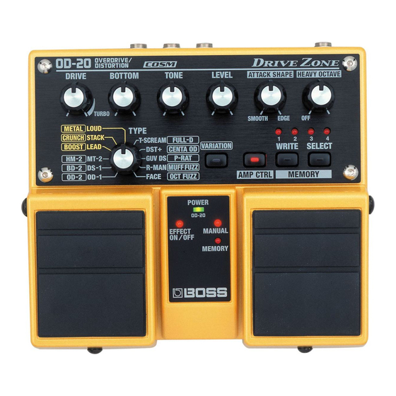
Page 14: Part Names And Functions
Part Names and Functions Front Panel fig.19 DRIVE Knob Adjusts the amount of distortion. Turning the knob to the right (clockwise) creates a stronger distortion and increases the volume. Turning this all the way to the TURBO range increases the effect even more. LEVEL Knob Adjusts the volume. - Page 15 Part Names and Functions MEMORY Number Indicator (1–4) The indicator for the currently selected MEMORY number (1–4) lights. The indicator flashes while the OD-20 is in write standby; the indicator flashes more rapidly while the write operation is in progress. MEMORY SELECT Button Use this to select a Memory (1–4),...
-
Page 16: Type List
* All product names mentioned in this document are trademarks or registered trademarks of their respective owners. Those companies are not affiliated with BOSS and have not licenced or authorized BOSS’s OD-20. Their marks are used solely to identify the equipment whose sound is simulated by BOSS’s OD-20. OD-1 Models the BOSS OD-1. -
Page 17: Power Indicator
This lights up when set to “MEMORY” (1–4). This blinks when you turn a knob to change the value of a setting, or put the OD-20 into write standby while a memory is selected, and blinks rapidly while data is being written. -
Page 18: Rear Panel
Part Names and Functions Rear Panel fig.22 INPUT Jack This is the input jack for connecting to the output of an electric guitar or other instrument or effects processor. * The INPUT jack also doubles as the power switch. The power comes on when a plug is inserted into the INPUT jack, and goes off when it is unplugged. -
Page 19: Changing How Memory Numbers Are Indicated
Select the pattern that provides the easiest way to check the memory in any particular environment. When using the OD-20 in dimly lit surroundings, you can confirm memory numbers more easily by using the Lighting Pattern 2 setting. -
Page 20: Returning Settings To Their Factory Defaults
Returning Settings to Their Factory Defaults You can restore the memories (1–4), pedal mode settings, and the MEMORY Number Indication to their original factory values. Memory Memory 1 (p. 23) Settings Memory 2 (p. 24) Memory 3 (p. 24) Memory 4 (p. 24) Pedal Mode (p. -
Page 21: Troubleshooting
Check the settings on the connected equipment (p. 3–4). Cannot switch amp channels properly Is the amp’s channel switching jack correctly connected to the OD-20’s AMP CTRL jack? Check the connections again. Does the amp’s channel switch match the polarity of the OD-20’s Amp Control? The OD-20’s Amp Control is shorted... -
Page 22: Sample Settings
Sample Settings Crunch with mild amp distortion fig.23 Overdrive with heavy distortion fig.24 Fat distortion sound fig.25 Not lit... - Page 23 Fairly bright metal sound fig.26 Radical fuzz fig.27 LOUD (Factory Default Memory 1) fig.28 Not lit Not lit Sample Settings...
- Page 24 Sample Settings LEAD (Factory Default Memory 2) fig.29 OD-1 (Factory Default Memory 3) fig.30 STACK (Factory Default Memory 4) fig.31 Not lit Not lit Not lit...
-
Page 25: Setting Memo
Setting Memo fig.32 fig.32 fig.32 Lit / Not lit Lit / Not lit Lit / Not lit... -
Page 26: Specifications
Specifications OD-20: Overdrive/Distortion Nominal Input Level -20 dBu Input Impedance Nominal Output Level -20 dBu Output Impedance Recommended Load Impedance 10 k or greater Dynamic Range 102 dB (IHF-A typ.) Controls EFFECT ON/OFF Pedal MANUAL/MEMORY Pedal DRIVE Knob BOTTOM Knob... - Page 27 This product complies with the requirements of European Directive 89/336/EEC. FEDERAL COMMUNICATIONS COMMISSION RADIO FREQUENCY INTERFERENCE STATEMENT This equipment has been tested and found to comply with the limits for a Class B digital device, pursuant to Part 15 of the FCC Rules.
- Page 28 G601735101 ’00-xx-xx-xxx...
Need help?
Do you have a question about the Drive Zone OD-20 and is the answer not in the manual?
Questions and answers