Table of Contents
Advertisement
Quick Links
Keithley Instruments
28775 Aurora Road
Cleveland, Ohio 44139
1-800-935-5595
tek.com/keithley
Introduction
The 7706 20-Channel Differential Multiplexer switching module offers 20 channels of 2-pole or 10 channels of
4-pole multiplexer switching with automatic CJC. It also offers two analog output channels, 16 digital outputs,
and one event counter/totalizer. You can use the event counter/totalizer to monitor and control system
components while making mixed signal measurements. The 7706 is ideal for RTD, thermistor, and
thermocouple temperature applications.
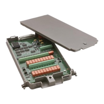
Item shipped may vary from model pictured here.
077145000 / June 2018
Model 7706 Multiplexer Module
Figure 1: 7706 Multiplexer Module
*P077145000*
Instructions for use with DAQ6510
1
Advertisement
Table of Contents

Subscribe to Our Youtube Channel
Related Manuals for Tektronix Keithley 7706


Summary of Contents for Tektronix Keithley 7706
- Page 1 Model 7706 Multiplexer Module Keithley Instruments Instructions for use with DAQ6510 28775 Aurora Road Cleveland, Ohio 44139 1-800-935-5595 tek.com/keithley Introduction The 7706 20-Channel Differential Multiplexer switching module offers 20 channels of 2-pole or 10 channels of 4-pole multiplexer switching with automatic CJC. It also offers two analog output channels, 16 digital outputs, and one event counter/totalizer.
-
Page 2: Wiring Procedure
Model 7706 Multiplexer Module Instructions for use with DAQ6510 The 7706 includes the following features: ▪ Twenty channels of analog input with 300 V,1 A capacity; 60 W, 125 VA maximum ▪ Sixteen channels of digital output ▪ One event counter/totalizer, which you can use to monitor and control system components and actions, such as fixtures, limit switches, pass/fail indicators, external voltage sources, loads, door closures, and revolutions ▪... - Page 3 Model 7706 Multiplexer Module Instructions for use with DAQ6510 Equipment needed: ▪ Flat-blade screwdriver ▪ Cable ties To wire the 7706: 1. Make sure all power is discharged from the 7706 module. 2. Using a screwdriver, turn the access screw to unlock and open the cover. Figure 2: Screw terminal access 3.
- Page 4 Model 7706 Multiplexer Module Instructions for use with DAQ6510 Figure 3: Channel designations for analog inputs 077145000 / June 2018...
- Page 5 Model 7706 Multiplexer Module Instructions for use with DAQ6510 Figure 4: 7706 screw terminal output, source, and sense channel designations 077145000 / June 2018...
- Page 6 Model 7706 Multiplexer Module Instructions for use with DAQ6510 4. Route the wire along the wire path and secure with cable ties as shown in the following figure. Figure 5: Wire dressing - fully wired module 5. Fill in a copy of the Connection log (on page 22).
- Page 7 Model 7706 Multiplexer Module Instructions for use with DAQ6510 7706 simplified schematic The 7706 has channels that are grouped into two banks of ten channels (twenty channels total). Backplane isolation is provided for each bank. Each bank also includes separate cold junction reference points. The first bank contains channels 1 to 10, while the second bank contains channels 11 to 20.
- Page 8 Model 7706 Multiplexer Module Instructions for use with DAQ6510 Figure 6: 7706 simplified schematic 077145000 / June 2018...
-
Page 9: Channel Usage
Model 7706 Multiplexer Module Instructions for use with DAQ6510 Channel usage When using remote communications to send commands, be aware of the following channel usage. Channels Description 1 to 20 Measurements such as voltage, resistance, temperature, frequency, and period 21 to 22 Eight-bit digital outputs 23 to 24 Sixteen-bit analog outputs (DAC) - Page 10 Model 7706 Multiplexer Module Instructions for use with DAQ6510 Before installing or removing a switching module, make sure the DAQ6510 power is turned off and disconnected from line power. Failure to comply may result in incorrect operation and loss of data in the memory. Required equipment: ▪...
-
Page 11: Operation
Model 7706 Multiplexer Module Instructions for use with DAQ6510 Before installing or removing a switching module, make sure the DAQ6510 power is turned off and disconnected from line power. Failure to comply may result in incorrect operation and loss of data in the memory. Required equipment: ▪... -
Page 12: Thermocouple Connections
Model 7706 Multiplexer Module Instructions for use with DAQ6510 Thermocouple connections Figure 7: Thermocouple connections Two-wire resistance and thermistor connections Figure 8: Two-wire resistance and thermistor connections 077145000 / June 2018... - Page 13 Model 7706 Multiplexer Module Instructions for use with DAQ6510 Four-wire resistance and RTD connections Figure 9: Four-wire resistance and RTD connections DC or AC voltage connections Figure 10: DC or AC voltage connections 077145000 / June 2018...
- Page 14 Model 7706 Multiplexer Module Instructions for use with DAQ6510 Digital outputs (channels 21 to 22) Use the 7706 digital outputs to control items such as indicators, fixtures, switches, solenoids, loads, and relays. The following figure shows a simplified schematic of the digital output. Figure 11: Simplified schematic of the digital output The digital output allows the use of an external power supply up to 42 V.
- Page 15 Model 7706 Multiplexer Module Instructions for use with DAQ6510 Set the digital outputs in 8-bit (byte) To set the digital output, send the decimal equivalent of the binary pattern. On each port, bit 7 is the most significant bit (MSB) and bit 0 is the least significant bit (LSB). This makes the pin 1 screw terminal of each digital port (TE2 and TE1) the LSB, and pin 10 the MSB.
- Page 16 Model 7706 Multiplexer Module Instructions for use with DAQ6510 Set digital value You can set a digital value using the front panel or remote commands. The following examples are for a card in slot 1. If the switching module is in slot 2, replace channel 121 with channel 221. Using the front panel: 1.
- Page 17 Model 7706 Multiplexer Module Instructions for use with DAQ6510 Setting the digital outputs in 16-bit (word) To set the digital outputs in 16-bit, send the decimal equivalent of the binary pattern (similar to 8-bit). The binary pattern is twice as long as the 8-bit pattern (requiring both digital output ports). Bit 15 is the most significant bit (MSB) and bit 0 is the least significant bit (LSB).
- Page 18 Model 7706 Multiplexer Module Instructions for use with DAQ6510 Set a 16-bit digital value You can set a 16-bit digital value using the front panel or remote commands. The following examples are for a card in slot 1. If the switching module is in slot 2, replace channel 121 with channel 221. Using the front panel: 1.
- Page 19 Model 7706 Multiplexer Module Instructions for use with DAQ6510 Figure 13: Typical digital output with no external power supply Reactive loads To prevent damage to the module, do not exceed the maximum signal level specifications of the module. For reactive loads, be sure to use voltage clamping and current surge limiting. 7706 operation is specified for resistive loads.
- Page 20 Model 7706 Multiplexer Module Instructions for use with DAQ6510 Analog outputs (channels 23 to 24) Analog output current limit is 5 mA (maximum). The 7706 contains two digital to analog converters (DACs). Use these analog outputs for tasks such as applying a voltage bias to DUTs or analog control.
- Page 21 Model 7706 Multiplexer Module Instructions for use with DAQ6510 Sample 2: Set analog output 2 (channel 24) to -5.5 V The following examples are for a card in slot 1. Set analog output 2 (channel 24). Using the front panel: 1.
-
Page 22: Loading Effects
Model 7706 Multiplexer Module Instructions for use with DAQ6510 Loading effects Loading of the voltage source is a consideration for low resistance loads. As the source resistance increases, the error caused by loading increases. The figure below shows the method used to determine the percent error due to loading, where: ▪... - Page 23 Model 7706 Multiplexer Module Instructions for use with DAQ6510 Channel Color Description INPUT SENSE CH10 CH11 CH12 CH13 CH14 CH15 CH16 077145000 / June 2018...
- Page 24 Model 7706 Multiplexer Module Instructions for use with DAQ6510 Channel Color Description CH17 CH18 CH19 CH20 CH21 CH22 CH23 CH24 CH25 IN– G– 077145000 / June 2018...
- Page 25 Model 7706 Multiplexer Module Instructions for use with DAQ6510 Totalizer Use the totalizer to count more than 4 billion on/off events, such as contact closures, revolutions, and power cycles. You can read or write the totalizer count from the front panel or the remote interface. For more advanced options, use the remote interface.
- Page 26 Model 7706 Multiplexer Module Instructions for use with DAQ6510 Threshold detection The totalizer can count events at a rate of up to 100 kHz. The count can be initiated manually or by configuring a scan. When counting, the totalizer can: ▪...
- Page 27 Model 7706 Multiplexer Module Instructions for use with DAQ6510 Gating provides specific control over when the totalizer readings are made. A gate is always interpreted if no gating signal is present. To control counting through the G+ screw terminal, send a TTL high signal to enable counting and a TTL low signal to disable counting.
-
Page 28: Scan Operation
Model 7706 Multiplexer Module Instructions for use with DAQ6510 Scan operation The limit subsystem and analog scan triggering works the same for the totalize function as for any other DAQ6510 function, except that only the upper limit is evaluated. The lower limit setting is ignored by the totalize function. - Page 29 Model 7706 Multiplexer Module Instructions for use with DAQ6510 When the limit is exceeded, the instrument starts the scan, as shown in the following figure. The instrument is configured to scan four channels: three DC voltage readings and the totalizer channel. The reading buffer stores all four readings.
- Page 30 Model 7706 Multiplexer Module Instructions for use with DAQ6510 Using SCPI commands: *RST ROUTe:CHANnel:WRITe 0, (@125) ROUTe:CHANnel:READ? (@125) SENSe:FUNCtion "VOLTage", (@101:105) SENSe:VOLTage:NPLC 0.01, (@101:105) ROUTe:SCAN:MONitor:CHANnel (@125) ROUTe:SCAN:MONitor:LIMit:UPPer 99999 ROUTe:SCAN:MONitor:MODE UPPer ROUTe:SCAN:COUNt:SCAN 100 ROUTe:SCAN:CREate (@101:105) INIT Reset the instrument. Set the totalizer to zero. Verify that the channel was set to 0.
- Page 31 Model 7706 Multiplexer Module Instructions for use with DAQ6510 Verification Use the procedures in this section to verify the analog outputs or the totalizer. These verification procedures require that the DAQ6510 be within its calibration interval. Verify the analog outputs Do not attempt to perform this procedure unless you are qualified, as described by the types of product users in the Safety precautions...
- Page 32 Model 7706 Multiplexer Module Instructions for use with DAQ6510 To verify the 7706 analog outputs: 1. Set the front panel TERMINALS switch to the REAR position. 2. Press the HOME key. 3. From the NON-SWITCH swipe screen, select Write. 4. Select channel 123, then OK. 5.
- Page 33 Model 7706 Multiplexer Module Instructions for use with DAQ6510 To verify the totalizer: 1. Connect the function generator to the totalizer IN+ and INterminals, as shown in the figure below. Leave gate inputs (G+ and G) open (gate always). 2. Set the threshold jumper to the TTL position (J2 closed). 3.
- Page 34 Model 7706 Multiplexer Module Instructions for use with DAQ6510 Figure 23: Verification - Totalizer connections 077145000 / June 2018...
-
Page 35: Recommended Test Equipment
Model 7706 Multiplexer Module Instructions for use with DAQ6510 Calibration Use the following procedures to calibrate the temperature sensors and analog outputs of the 7706. You must use remote communications and the SCPI command set to calibrate modules. For information on setting up remote communications, refer to "Remote communications interfaces"... -
Page 36: Temperature Sensor Calibration
Model 7706 Multiplexer Module Instructions for use with DAQ6510 Temperature sensor calibration Before calibrating the temperature sensor on the 7706, make sure that power has been removed from the module for at least two hours to allow module circuitry to cool down. After turning on the power during the calibration procedure, complete the procedure as quickly as possible to minimize module heating that could affect calibration accuracy. - Page 37 Model 7706 Multiplexer Module Instructions for use with DAQ6510 Analog output (DAC) calibration Set up calibration: 1. On the 7706 module, connect the channel 23 H and L outputs to the channel 1 H and L terminals (H to H; L to L).
- Page 38 Model 7706 Multiplexer Module Instructions for use with DAQ6510 Run calibration: 1. To unlock calibration, send: :CALibration:PROTected:CODE "KI006510" 2. To calibrate the 7706 analog output, send :CALibration:PROTected:CARD1:DAC:STEP0 3. Send the following commands to save and lock out calibration: :CALibration:PROTected:CARD1:SAVE :CALibration:PROTected:CARD1:LOCK 4.
-
Page 39: Factory Service
Factory service To return the switching module to Keithley Instruments for repair: ▪ Call the Repair Department at 1-800-833-9200 or send an email to RMAREQUEST@tektronix.com for a Return Material Authorization (RMA) number. ▪ Carefully pack the instrument in the original packing carton. -
Page 40: Safety Precautions
Safety precautions The following safety precautions should be observed before using this product and any associated instrumentation. Although some instruments and accessories would normally be used with nonhazardous voltages, there are situations where hazardous conditions may be present. This product is intended for use by personnel who recognize shock hazards and are familiar with the safety precautions required to avoid possible injury. - Page 41 For safety, instruments and accessories must be used in accordance with the operating instructions. If the instruments or accessories are used in a manner not specified in the operating instructions, the protection provided by the equipment may be impaired. Do not exceed the maximum signal levels of the instruments and accessories. Maximum signal levels are defined in the specifications and operating information and shown on the instrument panels, test fixture panels, and switching cards.
Need help?
Do you have a question about the Keithley 7706 and is the answer not in the manual?
Questions and answers