
Related Manuals for D-Link xStack Storage DSN-5210


Summary of Contents for D-Link xStack Storage DSN-5210
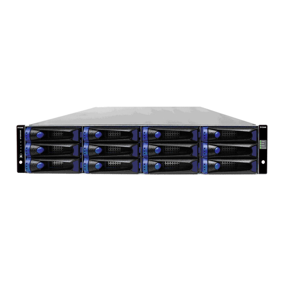
- Page 1 Storage D-Link xStack Storage iSCSI SAN Array Managed SAN Solution DSN-5210, DSN-5410 & DSN-5000 Hardware Reference Guide Version 1.0...
- Page 2 © 2009 D-Link Networks, Inc. All Rights Reserved D-Link Systems, Inc. makes no warranty of any kind with regard to this material, including, but not limited to, the implied warranties of merchantability and fitness for a particular purpose. D-Link Systems, Inc. shall not be liable for errors contained herein or for incidental or consequential damages in connection with the furnishing, performance, or use of this material.
- Page 3 VCCI Class A Notice of Export Controls Export of technical data contained in this document may require an export license from the United States government. Please contact D-Link Systems, Inc. for any export compliance questions. DSN-5000 series Hardware Reference Guide...
- Page 4 Document Revision Level Revision Date Description Version 1.0 January 27, 2009 Version 1.0...
- Page 5 This document is intended to assist users with installing the primary array and expansion array of the xStack Storage system from D-Link. This document assumes that users are computer literate, familiar with Storage Array Products, and have a basic understanding of storage products and concepts.
- Page 6 Contact Information You can find software updates and user documentation on the D-Link website. D-Link provides free technical support for customers within the United States and within Canada for the duration of the warranty period on this product. U.S. and Canadian customers can contact D-Link Technical Support through our website, or by phone.
-
Page 7: Table Of Contents
Unpacking the DSN-5000 series Primary Array ..........16 Items Supplied by the User ..............16 Connecting to the iSCSI Data Ports............16 3.5.1 xStack Storage DSN-5210 series Data Ports......... 17 3.5.2 xStack Storage DSN-5410 Data Port..........17 Connecting to the Management Port............17 Connecting the Power Cords .............. - Page 8 This Page Left Intentionally Blank viii Contents...
-
Page 9: Chapter 1 Introduction
Complete configuration and management of the storage system are available through the intuitive, graphical-based xStack Storage Management Center. For the latest information about supported drives, consult the Interoperability Matrix found on the D-Link Support Web site: support.dlink.com DSN-5000 series Hardware Reference Guide... -
Page 10: Models
Models The xStack Storage DSN-5000 series storage array is available in various models. The models differ according to the speed and host network interface. Table 1-1 lists the xStack Storage DSN-5000 series array models. Table 1-1. DSN-5000 series Storage Array Models Model Description DSN-5210 (single controller) System... -
Page 11: Benefits And Features
Benefits and Features High-performance, low-latency iSCSI storage system, with a highly integrated multifunction ASIC for fully featured, integrated storage virtualization High Availability with automatic failover when configured with dual controllers Modular design with expansion up to three chassis ... -
Page 12: System Overview
System Overview Figure 1-1 shows a typical DSN-5000 series storage system (primary array DSN-5210 or 5410) configuration in a Storage Area Network (SAN). The SAN shown is an Ethernet network used solely for exchanging data between the customer's host servers and the DSN-5000 series storage system. The Ethernet bandwidth used by the servers exchanging data with the DSN-5000 series storage system can be very high. -
Page 13: Chapter 2 Dsn-5000 Series Primary Array Layout
Chapter 2 DSN-5000 Series Primary Array Layout This chapter describes the hardware components on the DSN-5000 series primary array (DSN- 5210 & DSN-5410). The topics covered in this chapter are: Section 2.1, Front Panel Components Section 2.2, Rear Panel Components ... -
Page 14: Front Panel Components
Front Panel Components The front of the DSN-5000 series primary array enclosure has the following components (see Figure 2-1): Enclosure LEDs - four enclosure LEDs at the right side of the front panel provide status information about the DSN-5000 series primary array enclosure. For a description of these LEDs, see Table 2-1. - Page 15 Table 2-1. Enclosure LEDs Color Description Power Green ON = DSN-5000 series primary array is powered on. OFF = power is not being received. Fault Amber ON = a fault occurred with the power supply, fan, over temperature, internal module, or controllers.
-
Page 16: Rear Panel Components
10-Gigabit XFP iSCSI data port (iSCSI 0 for the DSN-5410) are located on the rear panel of the DSN-5000 series chassis controllers. Each iSCSI data port has port speed and port activity LEDs (see Table 2-3 for the xStack Storage DSN-5210 and Table 2-4 for the xStack Storage DSN-5410). - Page 17 Figure 2-5. Close-up View of DSN-5000 series Controller Rear Panel Redundant Controller or Filler Plate in Slot #1 Rear Panel Switches & LED’s 10G Data Port Management Port Primary Controller in Slot #0 Two Expansion Ports Figure 2-6. Rear View of the DSN-5410 with two controllers installed Figure 2-7.
- Page 18 Resets the system. This switch is recessed to prevent against accidental resets. Note: This switch simply reboots the system without changing your configuration. Restart This switch is reserved for future use. Table 2-6. Rear Panel LEDs (xStack Storage DSN-5210 and xStack Storage DSN-5410) Switch / LED Color Description Ready/Fault Primary array is powered off or performing its Power On Self Test.
-
Page 19: Side And Bottom Panel Components
Side and Bottom Panel Components The left and right sides of the DSN-5000 series primary array enclosure have rails for rack- mounting the unit. Product information labels will be found on the side, bottom, or rear of the unit. For rack-mount instructions, refer to Appendix B and to the documentation for the rack. - Page 20 This Page Left Intentionally Blank Chapter 2 DSN-5000 Series Primary Array Layout...
-
Page 21: Chapter 3 Installing The Dsn-5000 Series Primary Array
Chapter 3 Installing the DSN-5000 Series Primary Array This chapter describes how to install the DSN-5000 series primary array (DSN-5210 & DSN- 5410). The topics covered in this chapter are: Section 1.1, Site Considerations Section 3.2, Safety Considerations Section 3.3, Unpacking the DSN-5000 series Primary Array ... -
Page 22: Site Considerations
Site Considerations The site where you install the DSN-5000 series primary array can affect its performance. Therefore, choose a site that conforms to the requirements in the following sections. 3.1.1 General Considerations Observe the following considerations when selecting a location to install the DSN-5000 series primary array. -
Page 23: Rack-Mount Guidelines
3.1.3 Rack-mount Guidelines The DSN-5000 series primary array can be mounted in a standard 19-inch rack. Observe the following considerations for rack installations. For information about installing the system in a rack, refer to Appendix B and to the documentation for the rack. All rack-mounting hardware must be carefully assembled to properly support the ... -
Page 24: Unpacking The Dsn-5000 Series Primary Array
Unpacking the DSN-5000 series Primary Array After receiving the DSN-5000 series primary array, perform the following steps to ensure that the primary array and other contents arrived safely. 1. Inspect the outer shipping container for any damage that may have occurred in shipping. Report any sign of damage to the appropriate shipping agency. -
Page 25: Xstack Storage Dsn-5210 Series Data Ports
3.5.1 xStack Storage DSN-5210 series Data Ports The DSN-5210 primary array has eight 1-Gigabit RJ-45 data ports labeled iSCSI 0 through iSCSI 7 (see Figure 2-4 and Figure 2-5). These ports connect to your SAN using either a straight-through or cross-over RJ-45 Ethernet cable (the DSN-5210 primary array auto-senses the network link speed and type of cable used). - Page 26 Do not connect one NIC to the management and host network connection ports. Connect one NIC to the management port and connect another NIC in the same PC or a different PC to the host network connection port(s). Data Port Connection Management Port Connection Figure 3-1.
- Page 27 Network Switch To Host Servers Data Port Connections Management Port Connections Figure 3-3. Connecting Data and Management Ports (DSN-5210 with Dual Controllers) To Host Servers Data Port Connections Management Port Connections Figure 3-4. Connecting Data and Management Ports (DSN-5410 with Dual Controllers) DSN-5000 series Hardware Reference Guide...
-
Page 28: Connecting The Power Cords
Connecting the Power Cords The DSN-5000 series primary array has two power receptacles. Both must be used to connect the DSN-5000 series primary array to an AC outlet: 1. Plug the female end of one power cord into one of the 3-pronged power connectors on the back of the DSN-5000 series primary array. -
Page 29: Chapter 4 Dsn-5000 Expansion Array Layout And Installation
Chapter 4 DSN-5000 Expansion Array Layout and Installation This chapter describes the hardware components and installation instructions for the DSN-5000 expansion array (DSN-5000). The topics covered in this chapter are: Section 4.1, Expansion Array Front Panel Components Section 4.2, Expansion Array Rear Panel Components ... -
Page 30: 4.1 Expansion Array Front Panel Components
4.1 Expansion Array Front Panel Components The front of the DSN-5000 series expansion array enclosure has the following components (see Figure 4-1): LEDs - four enclosure LEDs at the right side of the front panel provide status information about the DSN-5000 series primary array enclosure. For a description of these LEDs, see Table 4-1. - Page 31 Lever Release Button Drive Status LEDs Figure 4-2. Close-up View of the Lever Release Button and Status LEDs on a Drive Carrier Table 4-2. Drive Carrier Status LEDs Color Description LED 1 Green This LED is reserved for future use. LED 2 Green OFF = no drive is installed (drive slot is empty).
-
Page 32: Expansion Array Rear Panel Components
Expansion Array Rear Panel Components The rear of the DSN-5000 expansion array enclosure has the following components (see Figure 4-4): One or two I/O modules, each containing two SAS connectors (HOST and EXP); the HOST connector connects the expansion array to the mini-SAS connector on the back of the DSN-5000 primary array. -
Page 33: Items Supplied By The User
3. Save the shipping container, foam, and antistatic bags in case you have to return the DSN-5000 expansion array. Returning the DSN-5000 expansion array in any other container is not advised. 4. Check the contents against the items referenced on the packing list. If any item is missing or damaged, notify a sales representative and/or the shipping agency. -
Page 34: Connecting To The Dsn-5000 Series Primary Array
Connecting to the DSN-5000 Series Primary Array To connect the DSN-5000 expansion array to the DSN-5000 series primary array, use the following procedure (and refer to Figure 4-5). 1. Facing the rear of the primary array, connect one end of the supplied primary array-to- expansion chassis cable to the right expansion connector labeled EXP0. -
Page 35: Connecting The Ac Power Cords
Connecting the AC Power Cords The DSN-5000 expansion array has two power receptacles. Both must be used to connect the DSN-5000 expansion array to an AC outlet: 1. Plug the female end of one power cord into one of the 3-pronged power connectors on the back of the DSN-5000 expansion array. - Page 36 This Page Left Intentionally Blank Chapter 4 DSN-5000 Expansion Array Layout and Installation...
-
Page 37: Appendix A Replacing And Upgrading Frus
DSN-5000 series primary array and DSN-5000 expansion array. FRUs that can be replaced or upgraded include: SAS drives Power supply modules Controller module (primary array only) I/O module (expansion array only) Connection of the serial port for diagnostics when working with D-Link Support DSN-5000 series Hardware Reference Guide... -
Page 38: Installing Or Replacing Drives
Installing or Replacing Drives Before you install or replace drives, plan where you will be placing the disk drives. If an array will not be fully populated with drives, be sure the drive slots contain drive trays and/or blank filler panels. For more information, see Figure 2-3 and Section 2.1. High Availability (HA) Note: A system using a single controller (DSN-5210 or DSN-5410) and its expansion array(s) may use SAS or SATA drives. -
Page 39: Replacing A Power Supply Module In The Primary Or Expansion Array
Replacing a Power Supply Module in the Primary or Expansion Array The power supply and fan reside on the same module. Facing the back of the array, one power supply/fan module appears on the left side of the array and a second module appears on the right side. -
Page 40: Replacing The Controller Module On The Primary Array
Replacing the Controller Module on the Primary Array Use the following procedure to replace a controller module on the primary array. 1. Power down the DSN-5000 series primary array and remove the power cords from the back panel. 2. Squeeze down on the top of the levers on either side of the controller module on the primary array and pull down to disengage the module, then pull the module straight out of the enclosure. -
Page 41: Replacing The I/O Module On The Expansion Array
Replacing the I/O Module on the Expansion Array Use the following procedure to replace the I/O module on the expansion array. 1. Power down the DSN-5000 series primary and expansion array and remove the power cords from the back panel. 2. -
Page 42: Connecting To The Diagnostic Serial Port
Connecting to the Diagnostic Serial Port The DSN-5210 series and DSN-5410 SAN arrays have a 115.2 Kbps RS-232-C stereo mini-jack connector on the right side of the rear panel (see Figure A-5). Using this port, you can: Reset the array to factory default settings (this deletes all custom settings, including all ... - Page 43 4. Type the number that corresponds to the action you want to perform. 5. Follow the screen prompts to complete the activity. DSN-5000 series Hardware Reference Guide...
- Page 44 This Page Left Intentionally Blank Appendix A Replacing and Upgrading FRUs...
-
Page 45: Appendix B Installing The System In A Rack
Appendix B Installing the System in a Rack This appendix describes how to install the DSN-5000 series primary and expansion arrays in a rack. The rack-mount kit comes with the following items: Two long main left and right rails Two medium left and right rear rails ... - Page 46 2. Assemble the rails that will accommodate the array in the rack. The long main left and right rails are used in all installations (these rails have a bottom piece on which the array sits in the rack). However, you must determine whether to use the two medium rear rails or the two short rear rails based on the depth of your rack.
- Page 47 If the rack has round and threaded holes, secure the rails using the supplied long screws only (there is no need to use the snap-in spring-loaded cage nuts and the E-shaped devices). 7. Secure the rails to the rack by inserting screws in the top and bottom holes on the left and right sides on the front of the rack (as shown in the following figure).
- Page 48 11. Locate the second-from-the-bottom hole on the front right side of the rack. This hole should be aligned with a hole in the flange or “ear” on the right front of the array. Place a screw in the hole in the array, then insert a screwdriver through the hole in the front flange of the array and tighten the screw to secure the array to the vertical supports, as shown in the following figure.
Need help?
Do you have a question about the xStack Storage DSN-5210 and is the answer not in the manual?
Questions and answers