Table of Contents
Advertisement
Quick Links
Installation instructions and Instructions for use
These instructions must be read
prior to installation
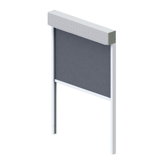
Concealed awning PM07 protect
Operating guidelines
Installation instructions and Instructions for use
Preliminary remarks HELLA
Concealed awning PM07 protect
With this HELLA product you have opted for a high-quality product with a most up-to-date
technology that can nevertheless be easily installed and operated. In these instructions we
describe the basic installation, commissioning and use.
For authorized specialist staff
For the consumer (user)
The following symbols will assist you with the installation or use and require a safety-
conscious conduct:
Attention!
This symbol indicates instructions that, if disregarded, can put the user in
danger.
Attention!
This symbol indicates instructions that, if disregarded, can potentially
result in damage to the product.
This symbol indicates instructions for use or helpful information.
This symbol requires you to act.
Attention!
This symbol indicates a risk of injury or danger to life due to an electric
shock.
This symbol indicates parts of the product, for which you will find
important information in these installation instructions.
This symbol indicates the
cleaning of the product.
Subject to technical modifications - Date of Issue
February/2023
and use!
This symbol indicates the
maintenance and repair of
the product.
Installation instructions and Instructions for use
Table of Contents
Preliminary remarks HELLA Concealed awning PM07 protect.............................................3
General notes.......................................................................................................................4
CE marking...........................................................................................................................5
Safety instructions ................................................................................................................6
Designated use ..................................................................................................................12
Interesting facts about awning covers ................................................................................16
Servicing, maintenance and repair .....................................................................................18
Operating guidelines...........................................................................................................21
Operating principle Somfy Maestria+ 50 io.........................................................................22
Operating principle of the elero drives ................................................................................23
Before installation...............................................................................................................24
Part designation PM07 - box ..............................................................................................31
Part designation PM07 - Plaster base ................................................................................32
Part designation PM07 - Insulation 20/40mm.....................................................................33
Part designation PM07 - standard guide rail 32x55 mm ....................................................34
Part designation PM07 - guide rail 32x97/115/130 mm ......................................................35
Drive duct ...........................................................................................................................36
Installation options - Guide rail 32x97/115/130 mm............................................................41
Installation options - guide rail 32x97/115/130 incl. adapter profile ....................................44
Direct installation ................................................................................................................47
Adjusting the motor.............................................................................................................53
Activation guidelines for electric drives...............................................................................54
Connection directives for motor drive .................................................................................55
Functional check ................................................................................................................59
Commissioning...................................................................................................................60
Removal roller tube with drive ............................................................................................61
Installation roller tube with drive .........................................................................................66
Removal in general.............................................................................................................73
Handing over report (for the fitter) ......................................................................................74
Handing over report (for the user) ......................................................................................75
Installation instructions and Instructions for use
General notes
Questions
In case of questions concerning the installation or the use of your product, please consult
your authorized specialist shop.
Spare parts/repairs
Spare parts are available at your HELLA specialist shop. Only spare parts that are
approved by HELLA are allowed to be used.
Warranty/guarantee
Precondition for warranty and guarantee is a correct and regular maintenance of the sun
protection device (at least once a year).
Warranty claims are subject to statutory limitation periods. Service parts are excluded
from the warranty; the same applies for changes in color and changes in characteristics
caused by UV radiation.
As the composition or the chemical and physical properties of the plasters used are
beyond our control, the resistance of our systems to corrosion cannot be guaranteed,
Liability
In case of non-observance of the directions and information given in these instructions
and in case of improper operation or unintended use, the manufacturer shall not accept
any warranty claims concerning any damage to the product. In these cases, the liability
for consequential damage to any parts or persons is ruled out as well.
Legal notes
The graphs and texts of these instructions were carefully prepared. We cannot be held
liable for any errors and their potential consequences! Subject to technical modifications
to the product and to these instructions! These instructions include copyrighted
information. All rights reserved! The listed product or brand names are trademarks of the
respective owners.
3
4
Subject to technical modifications - Date of Issue
February/2023
Advertisement
Table of Contents

Subscribe to Our Youtube Channel
Related Manuals for Hella PM07 protect


Summary of Contents for Hella PM07 protect
-
Page 1: Table Of Contents
Questions In case of questions concerning the installation or the use of your product, please consult With this HELLA product you have opted for a high-quality product with a most up-to-date your authorized specialist shop. technology that can nevertheless be easily installed and operated. In these instructions we describe the basic installation, commissioning and use. -
Page 2: Ce Marking
CE marking Safety instructions The HELLA concealed awning PM07 protect (side seam guided) is in compliance with the These installation instructions refer to prefabricated elements, that (1) for declaration of performance according to the Construction Products Regulation; if the unit is... -
Page 3: Designated Use
- Protection of the insulating material by applying a plaster base Recommended maximum wind limit values - Covering the upper surface (do not use transparent foils!) The HELLA concealed awnings of the type PM07 protect are defined according to CE and are in accordance with EN 13561. Wind resistance: Class 3 corresponds to wind force 6 on the Beaufort scale (10.8-13.8... -
Page 4: Interesting Facts About Awning Covers
Installation instructions and Instructions for use Designated use Designated use Wind resistance - Specification of wind resistance classes according to EN Recommendations of operation for side seam guided HELLA vertical awnings 13561:2004+A1:2008 according to IVRSA in connection with the directive (EU) 2019/1188... -
Page 5: Servicing, Maintenance And Repair
Improper repair works may cause both risk of injury to persons or damage to the units. Maintenance: Repair works must be carried out by a HELLA specialist company or a partner company of HELLA. All inspection and maintenance works Only use original spare parts from HELLA. -
Page 6: Operating Guidelines
Installation instructions and Instructions for use Installation instructions and Instructions for use Operating guidelines Operating principle Somfy Maestria+ 50 io Motor drive: Obstacle detection in down direction: By operating a switch, a hand-held radio - Unit moves down transmitter or an automatic device, the cover - Obstacle moves up or down. -
Page 7: Before Installation
Installation instructions and Instructions for use Installation instructions and Instructions for use Before installation Before installation Single installation Reviewing the order information: Combination Reviewing the order information: Ordering dimensions: Ordering dimensions: Complete width (ordering width) = outer edge Complete width (ordering width) of the guide rail Complete height (ordering Complete height (ordering height) -
Page 8: Part Designation Pm07 - Box
Installation instructions and Instructions for use Installation instructions and Instructions for use Before installation Before installation Version with cable whip and Hirschmann connector in the box Drive side on the left or right side (seen from the inside): 100/115/130 Drive side on the left side Drive side on the right side Legend Cable exit towards the top... -
Page 9: Part Designation Pm07 - Insulation 20/40Mm
Installation instructions and Instructions for use Installation instructions and Instructions for use Part designation PM07 - Insulation 20/40mm Part designation PM07 - standard guide rail 32x55 mm with box size 100 mm, 115 mm and 130 mm with box size 100 mm, 115 mm and 130 mm Legend Plaster base Edge protection for unwinding profile... -
Page 10: Drive Duct
Installation instructions and Instructions for use Installation instructions and Instructions for use Drive duct Installation options - standard guide rail 32x55 mm Providing a duct in the wall or window frame - Provide a duct boring with Direct installation ø10 mm! 100/115/130 - Avoid sharp edges at the duct or remove them! -
Page 11: Installation Options - Guide Rail 32X97/115/130 Mm
Installation instructions and Instructions for use Installation instructions and Instructions for use Installation options - Guide rail 32x97/115/130 mm Installation options - Guide rail 32x97/115/130 mm Direct installation - box size 100 mm, 115 mm and 130 mm Direct installation with plaster base - box size 100 mm, 115 mm and 130 mm 100/115/130 Vertical section PN 7... -
Page 12: Installation Options - Guide Rail 32X97/115/130 Incl. Adapter Profile
Installation instructions and Instructions for use Installation instructions and Instructions for use Installation options - guide rail 32x97/115/130 incl. Installation options - guide rail 32x97/115/130 incl. adapter profile adapter profile Direct installation - box size 100 mm, 115 mm and 130 mm Direct installation - box size 100 mm, 115 mm and 130 mm Vertical section Horizontal section... - Page 13 Installation instructions and Instructions for use Installation instructions and Instructions for use Direct installation Direct installation Direct installation from the front 5. Pass the motor cable 6. Fit the box to the guide through the wall opening and rails and lower to the stop. fix the guide rails to the mounting base by using the Risk of injury or danger to...
-
Page 14: Adjusting The Motor
Installation instructions and Instructions for use Installation instructions and Instructions for use Adjusting the motor Activation guidelines for electric drives If the unit is delivered with a The motors we use are drives with integrated planetary gear, brakes, limit motor drive, the end positions stops at the top and at the bottom, and thermo cut-off switches, also not are not pre-adjusted. -
Page 15: Functional Check
Installation instructions and Instructions for use Installation instructions and Instructions for use Connection directives for motor drive Connection directives for motor drive The electrical connection is described in the enclosed instructions of the manufacturer of Directions for radio motors: the motor drive and must be carried out in accordance with these instructions For elero radio-controlled tube motors, the connections no. - Page 16 Installation instructions and Instructions for use Installation instructions and Instructions for use Removal roller tube with drive Removal roller tube with drive At least two persons are 6. Move the roller tube with required for the following the cover towards the work steps.
-
Page 17: Removal Roller Tube With Drive
Installation instructions and Instructions for use Installation instructions and Instructions for use Removal roller tube with drive Installation roller tube with drive 16. Detach the motor bearing from the pins and lower the roller tube. 17. Loosen the threaded joint between the motor bearing and the drive and remove the motor bearing. - Page 18 Installation instructions and Instructions for use Installation instructions and Instructions for use Installation roller tube with drive Installation roller tube with drive 6. Attach the circlip to the 8. Wind up the cover to the telescopic roller cap and front rail. secure it by means of a screw.
-
Page 19: Removal In General
Switch the unit dead and take safety precautions against unintentional Dear Customer, switching on. We are glad that you have opted for a HELLA brand product. Our units are fabricated with greatest care and many years of experience. The removal is carried out in reverse order to the installation.
Need help?
Do you have a question about the PM07 protect and is the answer not in the manual?
Questions and answers