
Related Manuals for Hella APS-R


Summary of Contents for Hella APS-R
- Page 1 Installation and configuration manual Advanced People Sensor APS-R and APS-R-PoE, SW 1.2 HAGL-120-00079, 2017-06, APS-R, APS-R-PoE, SW 1.2...
- Page 2 Till 07.07.2017 the company headquarters will be located at Treskowstrasse 14, 13089 Berlin © 2017 HELLA AGLAIA Mobile Vision GmbH, Berlin (hereinafter 'Hella Aglaia') The reproduction, distribution and utilization of this document as well as the communication of its contents to others 09.06.2017...
- Page 3 Unless expressly agreed upon in writing, HELLA AGLAIA Mobile Vision GmbH is not obligated to notify the owner or user of the devices described in this manual (including the respective software) of any revisions, updates, or modi- fications without further request.
-
Page 4: Table Of Contents
Table of contents Table of contents Overview............................... 6 General information..........................7 About this document........................7 About the manufacturer....................... 7 Limitation of liability........................8 Scope of delivery......................... 8 Use of the Advanced People Sensor..................8 Data protection..........................9 Structure and function........................10 Hardware........................... - Page 5 Table of contents Troubleshooting......................... 49 Disposal.............................. 51 Appendix............................52 Detection area........................... 52 Ordering Information......................... 52 Menu Structure.......................... 53 List of used IP ports........................56 Software licenses........................57 CE Declaration of Conformity....................58 Glossary and abbreviations......................60 Index..............................62 The reproduction, distribution and utilization of this document as well as the communication of its contents to others 09.06.2017 without express authorization is prohibited.
-
Page 6: Overview
Overview Overview The Advanced People Sensor (APS) counts persons within the configured area/monitored area based on stereoscopic imaging and image processing. The counting data is stored internally and can be transferred via different interfaces for external processing. Fig. 1: People sensing Advanced People Sensor (APS) Configured area/monitored area Counting line... -
Page 7: General Information
This document is addressed to system integrators. Software and hardware version All information in this manual refers to software version 1.2 and hardware APS-R, APS-R-PoE. Modifications to the functionality which will be implemented through future software updates will be described in separate release notes or in an updated version of the manual. -
Page 8: Limitation Of Liability
The obligations agreed upon in the delivery contract, General terms and conditions and delivery conditions of Hella Aglaia as well as any legal regulations applicable at the time of the contract con- clusion apply. -
Page 9: Data Protection
General information Data protection 2.6 Data protection The Advanced People Sensor was classified to be harmless according to German law in terms of data protection by a declara- tion of the Berlin Commissioner for Data Protection and Freedom of Information dated September 10 2009, since individuals cannot be identified in normal device use and the data is solely intended for statistical purposes. -
Page 10: Structure And Function
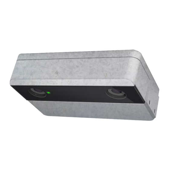
Structure and function Hardware Structure and function 3.1 Hardware APS-R, APS-R-PoE Fig. 2: Hardware APS-R/APS-R-PoE I/O-interface (D-SUB) Fixing points (2 x 2 M5) HDR camera Status LED HDR camera Ethernet interface (M12) Ground stud (metric thread M5) For detailed information about the interfaces, Ä... - Page 11 The four jumpers enable 16 dif- 9 10 11 12 13 14 15 ferent combinations. Fig. 3: Code jumper for APS-R – The code jumper ports are NOT suitable as regular inputs for external process signals.
- Page 12 Note that the available options are software-driven and may IN0- IN0+ change over time. +24 V DC The APS-R has one usable input (IN0), the APS-R-PoE has two usable inputs (IN0 and IN1). Fig. 5: Wiring example APS-R Electrical characteristics: LOW: U <...
- Page 13 Structure and function Hardware Installation heights, areas covered The device will be positioned above the area to be monitored. The installation height shall be between 200 cm and 400 cm above the floor. The absolute minimum is 190 cm. Height Area covered 200 cm 191 x 160 cm...
-
Page 14: Functionality
Structure and function Functionality 3.2 Functionality The device continually acquires stereoscopic video images in its visual range. Fig. 9: People sensing Advanced People Sensor (APS) Configured area/monitored area Counting line The integrated software evaluates the stereoscopic images. Per- sons within the monitored area are recognized automatically and their movements are tracked across the subsequent images. - Page 15 Structure and function Functionality Normal state. Covered One or both cameras covered, e.g. by a sticker. Too dark Illumination is too low for proper function or both cameras are completely covered and shown a black image. Too bright more hypothetical, because direct sunlight and reflexions from sunlight do not cause "too bright"...
-
Page 16: Re-Entry And Re-Exit Detection ('Repassing' / 'U-Turns')
Structure and function Re-entry and re-exit detection ('Repassing' / 'U-turns') 3.3 Re-entry and re-exit detection ('Repassing' / 'U-turns') In many cases you do not want to count persons crossing a counting line if they turn around within the monitored area and cross the counting line again. -
Page 17: Technical Data
Technical data Mechanical data Technical data 4.1 Mechanical data APS-R, APS-R-PoE Category Description Dimensions approx. 141 mm x 98 mm x 35 mm (see Fig. 11) Weight 440 g Material Aluminum 140. 80 25.40 59.20 9.50 25.50 Ground stud M5 Cone of view 140.80... -
Page 18: Hardware Interface Specifications
Transmit data + Receive data + Transmit data - Receive data - Shield Fig. 12: M12 Ethernet interface Compatibility of APS-R-PoE and PoE switches APS-R-PoE Port M12 D-coded (4 pins) Port M12 D-coded (4pins) Port M12 X-coded (8pins) Port RJ45 PoE Switch "Mode A", "Midspan",... -
Page 19: I/O-Port
Technical data Hardware interface specifications > I/O-Port 4.2.2 I/O-Port Pin Allocation APS-R-PoE Pin no. Name Description Reset Reset Pin 9 10 11 12 13 14 15 (leave open, only required for correc- tive maintenance) Fig. 13: D-SUB I/O Interface OUT0 +... - Page 20 Technical data Hardware interface specifications > I/O-Port Pin Allocation APS-R Pin no. Name Description Reset Reset Pin 9 10 11 12 13 14 15 (leave open, only required for correc- tive maintenance) Fig. 14: D-SUB I/O Interface OUT0 + Programmable output +, potential-...
-
Page 21: Electrical Data
Remark about power interruptions: With regard to the use in trains, the APS-R-PoE will withstand short power interruptions of approx. 5 ms, which is close to EN 50155 class S2. This behavior deviates from the PoE specification IEEE 802.3af, which requires an instant shutdown at low voltage. -
Page 22: Optical Data
Technical data Optical data Supply voltage APS-R Category Compliance Description Power supply EN 50155 = 12 to 30 V DC IEEE 1476 Protected against short- circuit and inverse polarity Power EN 50155 class S2 Ability to withstand interruptions short power fails of... -
Page 23: Environmental Conditions
Technical data Environmental conditions 4.5 Environmental conditions Category Compliance Description Ambient EN 50125-1 class T3 Operation: temperature -25 °C to 70 °C Storage: -40 °C to 85 °C Extended low temper- ature range: Cold start between -40 °C and -25 °C will not cause damage. -
Page 24: Product Labels
Software / Firmware version Preinstalled licences Hardware model Part number 10 Product name (e.g. APS-R) Fig. 15: Identification label 11 Manufacturer logo Do Not Open Label The small label with the warning "do not open device" at the side of... -
Page 25: Installation
Installation Requirements Installation 5.1 Requirements Consider the following requirements when selecting the mounting position: Fig. 17: Mounting position Ensure that the mounting position and the holder / protective housing provide sufficient stability. Ensure that the mounting position is in the right place: –... -
Page 26: Recessed Mounting
Connect the network cable ( Fig. 20/2). Plug in the configured D-Sub ( Fig. 20/1) connector. If you don't use I/O ports or predefined door configurations with the APS-R-PoE skip this step. Place the mounted unit in the recess. Fix the installation frame with 4 screws. -
Page 27: Configuration
Fig. 21: Examples to connect A Connecting to a local network (e.g. in a train or bus) with DHCP server and APS B Connecting directly to a single APS-R-PoE C Connecting directly to a single APS-R Installation Equipment Connecting to a local PC or tablet ( Fig. - Page 28 Access your router or DHCP Software to find the IP address used by the device. Search for the unique MAC address of the device. ð The MAC address starts with 00:0b:91 for Hella Aglaia devices. Fig. 22: Fetching the used IP address (example) Start a web browser and enter the IP address (e.g.
-
Page 29: Basic Operations
Configuration Basic operations Enter login password depending on whether “Login Read- Only” or “Login for Setup” access is needed. Click the corre- sponding login button. The password can be changed in the configura- tion. The default passwords are: – user for “Login Read-Only” . –... - Page 30 Configuration Basic operations Camera View Some of the menu categories use a camera view to configure areas or lines. This view can be a live view, a still image or an optional privacy image. Mark objects Fig. 25: Camera view Camera View Show/Hide button for overlay information Slider control for brightness...
- Page 31 Configuration Basic operations Fig. 27: Topic block Obstructions before and after activation Edit The information shown in a topic block correspond to the activation of options. Topic blocks contains input fields, activation buttons and buttons for saving data or to revert to previous settings. Navigation Bar The user interface has a navigation bar on the left.
-
Page 32: Start Page - Live View
Configuration Start Page - live view Changing Values, Areas and Lines Range Floor Area Obstructions Fig. 29: Configuration options Polygon line Polygon point Overlay views buttons Reset button Save button Input field Edit button Changing Values Click in an input field or use the [tab] key to go to the next input field or button. -
Page 33: Camera Position
Configuration Camera Position Camera View Click the “play” button ( Fig. 30/4) for a live view. The “play” button change to “pause” button during live view. Click the “forward” button ( Fig. 30/3) to refresh view if live view paused. The “forward” button is deactivated during live view. - Page 34 Configuration Camera Position Camera Position The device has an inbuilt tilt measurement. The angles are meas- ured relative to the center of the earth. Click the “Refresh” button ( Fig. 33/6) to perform a new measurement. Compare the 'set' angles with the 'measured' pitch angle ( Fig.
- Page 35 Configuration Camera Position The height is measured with the “Refresh” button in the topic block “Camera Position” ( Fig. 33/6). Applying the measured height ( Fig. 34/8) with the “greater than” button ( Fig. 34/3) into the input field ( Fig. 34/5) sets the install height of the counter.
- Page 36 Configuration Camera Position Click the “Auto adjust” button ( Fig. 36/2) to apply these new measured values to all of the polygon points. A single polygon point height value can be changed by selecting it in the live view and either: –...
-
Page 37: Counting
Configuration Counting Click the “Reset” button ( Fig. 38/4) to go back to previous settings. Click the “Clear” button ( Fig. 38/6) to erase all marks. 6.5 Counting The device can use up to 10 individual bi-directional counting lines. More than 1 line is an optional feature that requires a license for activation. -
Page 38: Data Recording
Configuration Data Recording Enter a unique “Name” ( Fig. 40/7) for the counting line. This is used in the user interface as well as in data files. Specify the delay in both directions ( Fig. 40/8 and Fig. 40/10) to handle re-passing and U-turns. Choose a time from the drop down list. - Page 39 Configuration Data Recording Tick “Enable Video Recording” checkbox ( Fig. 42/1) for acti- vation. Choose a “Video Mode” ( Fig. 42/2) from the drop down list. Tick Trigger checkbox “In0” or “In1” ( Fig. 42/3) to start/stop video recording automatically with trigger signal. Checkout “Inverted”...
- Page 40 Configuration Data Recording Off: No data recording. Time Triggered: – Set a “Completion Interval” to define the period for a data file. After this period each data file is completed. New data is recorded in a subsequent file. Choose an interval between 15 min and 1 day from the drop down list.
-
Page 41: Network
Configuration Network 6.7 Network Use the Network Communication Settings to set up the IP commu- nication of the device inside your network and to your data server. Network Status This topic block shows the network settings which have either been assigned automatically by a DHCP server or have been set manually. - Page 42 Configuration Network Proxy Settings Sometimes the internet cannot be reached directly but through a so called proxy server. If this is the case in your installation, set the Proxy Settings accordingly. Set them as a standard HTTP connec- tion or as a secured HTTPS connection. If required enter the username and password for the proxy usage.
-
Page 43: Other Settings
Configuration Other Settings VDV-301 Settings If “Use VDV-301 Protocol” is activated ( Fig. 51/4), set a Device ID ( Fig. 51/1) as identification. Click the “Save” button ( Fig. 51/3) to save all the settings in the device. Click the “Reset” button ( Fig. 51/2) to go back to previous settings. -
Page 44: Service Tools
Configuration Service Tools HMI Login Settings Here you can change the passwords for the two login modes. You also can uncheck the Password for Read-Only access ( Fig. 54/1) which disables the password request upon login for read-only mode. Enter the new password for Read-Only access ( Fig. 54/2) twice. - Page 45 Diagnosis Data For Hella Aglaia customer support, it can be useful to provide diagnostic data that can be exported from the device. Click “Get Diagnosis Data” ( Fig. 60/1) to download the file.
-
Page 46: About
Configuration About Factory Reset Under certain circumstances it might be necessary to reset all the parameter settings of the device to their factory default set- tings. Click “Start Factory Reset” ( Fig. 62/1) to reset the parameters to the default settings of the installed firmware version. Follow the instructions. -
Page 47: Diagnostics
Configuration Diagnostics Network Status Although some settings can be manually set, when using DHCP some of the network settings are received from the router or other DHCP servers. The Hostname identify the device by a given name and is also used in protocols and saved files. - Page 48 Configuration Diagnostics Track Object Settings ID: 7711 Height: 183 Age: 5051 Class:1 WbD: 0 ID: 7713 Height: 178 Age: 4368 Class:1 WbD: 0 Range Floor Area R color HMI rec 20 fps Info Fig. 69: Settings for Tracked Objects Fig. 70: Diagnostics Live View Select the type of information to be shown at the camera view: Click “Top”...
-
Page 49: Cleaning, Maintenance And Troubleshooting
Cleaning, maintenance and troubleshooting Troubleshooting Cleaning, maintenance and troubleshooting 7.1 Cleaning Special tool: Lint-free cloth Commonly available neutral cleaners diluted with water Optimal counting accuracy can be achieved only if the view of the cameras is not obstructed. Check the cover plate or outside housing for dirt, scratches and stickers at regular intervals. - Page 50 Cleaning, maintenance and troubleshooting Troubleshooting Fault description Cause Remedy No counting results Wrong configura- Check in the user interface: tion If counting lines are defined and correct in the passage- ways. Counting lines are in the defined floor area. On both sides are at least 40 cm distance to the edge of the floor area.
-
Page 51: Disposal
After decommissioning, the product shall be recycled as waste electronic in an environmentally safe way. In the European Union, the WEEE Directive 2012/19/EU applies. Hella Aglaia will recollect its own electronic products free of charge and take care of the fur- ther processing. -
Page 52: Appendix
220.5 13.12 21.88 18.37 9.2 Ordering Information Product Product Description Order no. Old order no. APS-R Advanced People Sensor 013.928-007 510239 with local DC power supply for ceiling heights from 2.0 m - 4.00 m APS-R-PoE Advanced People Sensor 013.929-007... -
Page 53: Menu Structure
10 counting lines can be shown and also recorded. Accessories Accessory Description Order no. Old order no. APS-R installation kit recessed Installation kit for recessed 226.168-017 white mounting with adjustable angle between 0 and 44 degree APS-R installation kit recessed Installation kit for recessed 226.168-007... - Page 54 Network Status IP, Gateway, DNS, etc. System Health Status Uptime, CPU temperature, cause of last reboot, etc. Contact Addresses Hella Aglaia contact data Diagnostics Camera view Adjustable camera view Counts Live counting results The reproduction, distribution and utilization of this document as well as the communication of its contents to others 09.06.2017...
- Page 55 Appendix Menu Structure Menu View Comment Tracked Object List Visuali- Display options for tracked objects inside the zation camera view Logout The reproduction, distribution and utilization of this document as well as the communication of its contents to others 09.06.2017 without express authorization is prohibited.
-
Page 56: List Of Used Ip Ports
Appendix List of used IP ports 9.4 List of used IP ports This list provides all network ports that are used by the APS. Most of them are needed only with optional functions. Consult this list for your firewall and router configuration. Establishing communication direction ➨... -
Page 57: Software Licenses
Appendix Software licenses Direction Port TCP/UDP Description OpenVPN APS➨ 1194 Establish virtual point-to-point connection to a server (Virtual Private Network) configurable ➨APS Secure terminal access to device (Secure SHell) ➨APS SFTP Logfile download (Secure File Transfer Protocol) ➨APS telnet Terminal access to device 9.5 Software licenses The following licenses apply to the software components used in the device:... -
Page 58: Ce Declaration Of Conformity
Appendix CE Declaration of Conformity 9.6 CE Declaration of Conformity Fig. 71: APS-R CE-Declaration The reproduction, distribution and utilization of this document as well as the communication of its contents to others 09.06.2017 without express authorization is prohibited. Offenders will be held liable for the payment of damages. - Page 59 Appendix CE Declaration of Conformity Fig. 72: APS-R-PoE CE-Declaration The reproduction, distribution and utilization of this document as well as the communication of its contents to others 09.06.2017 without express authorization is prohibited. Offenders will be held liable for the payment of damages.
-
Page 60: Glossary And Abbreviations
Glossary and abbreviations Glossary and abbreviations Advanced People Sensor Second generation people sensor, successor of the APC Comma separated values File format where values are separated by commas. Those files can be imported into Microsoft Excel. DHCP Dynamic Host Configuration Protocol Protocol and service dynamically distributing network config- uration parameters, such as IP address and servers. - Page 61 Glossary and abbreviations Push service Sending data from the APS to a data server (the connection is established by the APS) Remote Access Service - web service to remote access sensors SOAP Network protocol for exchanging data between systems and implementing remote procedure calls Transmission Control Protocol One of the core data transfer protocols of the Internet Pro-...
-
Page 62: Index
Notes ........7 APS-R ......10 The reproduction, distribution and utilization of this document as well as the communication of its contents to others 09.06.2017... - Page 63 Index NTP ........43 Support ....... . . 7 System health status .
- Page 65 HELLA AGLAIA Mobile Vision GmbH Ein Unternehmen der HELLA Gruppe Ullsteinstrasse 140 12109 Berlin...
Need help?
Do you have a question about the APS-R and is the answer not in the manual?
Questions and answers