Advertisement
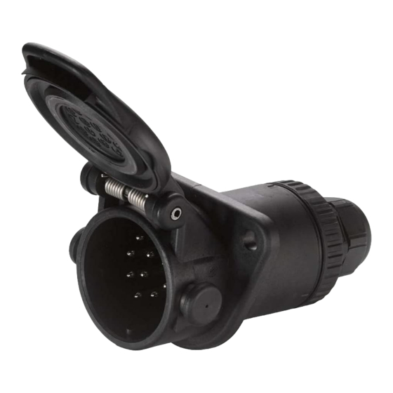
Montageanleitung 15-P-Steckdose 24 V ISO 12098
mit PG-Kabelverschraubung für Kabelanschluss ø12-18)
mounting instruction for 15P-socket 24 V according to ISO 12098
(with PG-cable gland screw for cable connection ø12-18)
Verpackungsinhalt:
Pos.
Benennung
1
Dosengehäuse
2
Kabelverschraubung
3
Bajonettverschluss
4
Kontakteinsatz
-
Montageanleitung
Montageanleitung 15 P Steckdose 24 V
1.
Kabelverschraubung (Teil 2) mit Bajonettverschluss (Teil 3) fest verschrauben.
2.
Mehradriges Kabel 60mm abmanteln und durch die Kabelverschraubung mit Bajonettverschluss (Teil 2 und 3)
schieben.
3.
Einzeladern an Kabel 7mm abisolieren.
4.
Kontakteinsatz (Teil 4) nehmen und die Schraube von Kontakt Nr. 15 lösen. Die abisolierte Einzelader Nr. 15 in
die hintere Kontaktbohrung bis Anschlag einschieben und die Schraube wieder anziehen. Entsprechend ist auch
mit Kontakt Nr. 14, 13 und so weiter in dieser Reihenfolge zu verfahren. Durch leichten Kabelzug prüfen, ob alle
Einzeladern richtig verschraubt sind.
5.
Innenliegende Dosendichtung mit Gleitmittel benetzen. Kontakteinsatz (Teil 4) in Dosengehäuse (Teil 1) ein-
schieben. Achtung: Teile sind codiert, nur eine Stellung möglich.
6.
Bajonettverschluss (Teil 3) an Stirnseite und O-Ring mit Gleitmittel benetzen, in Dosengehäuse (Teil 1) einführen
und mit einer kleinen Drehung verrasten. Achtung! Rastkennung muss übereinstimmen.
7.
Überwurfmutter der Kabelverschraubung (Teil 2) fest anziehen.
8.
Abschließend Sicht- und Funktionsprüfung vornehmen.
035465 (030204)
Anzugsmoment 0,6-0,8Nm
Starting torque 0,6-0,8Nm
Stk.
1
1
1
1
1
HELLA-Artikelnummer: 8JB 007 242-011
HELLA-part number:
content of packaging:
Pos.
title
quantity
1
socket casing
2
cable gland screw
3
bayonet catch
4
contact insert
-
mounting instruction
Mounting instruction for 15 pin socket 24 V
1.
Screw up tightly the cable gland screw (piece no.2) with the bayonet catch (piece no. 3).
2.
Strip the multi-core cable by about 60 mm and slide it through the screwed cable gland with
bayonet catch (pieces no.2+3).
3.
Strip the individual cores of cable by 7 mm.
4.
Take contact insert (piece no. 4) and loose the screw of contact no. 15. Push the stripped
core no. 15 into the rear contact hole until it stops then tigthen the screw. Do the same with
contact no. 14, 13 and so on in this order. Check the screwed cores by pulling the cables
softly.
5.
Wet the sealing inside the socket casing with a sliding means. Push the contact insert
(piece no. 4) into the socket casing (piece no. 1).
6.
Wet the bayonet catch (piece no.3) at the front and the o-ring seal with a sliding means;
push the bayonet catch into the socket (piece no. 1) and lock it by turning. Attention to cor-
responding catch-markers.
7.
Screw up tightly the union nut of the screwed cable gland (piece no. 2).
8.
Carry out a final visual examination and functional testing.
8JB 007 242-011
Anzugsmoment 5-6Nm
Starting torque 5-6Nm
1
1
1
1
1
®
Advertisement
Table of Contents

Related Manuals for Hella 8JB 007 242-011


Summary of Contents for Hella 8JB 007 242-011
- Page 1 Montageanleitung 15-P-Steckdose 24 V ISO 12098 HELLA-Artikelnummer: 8JB 007 242-011 ® mit PG-Kabelverschraubung für Kabelanschluss ø12-18) mounting instruction for 15P-socket 24 V according to ISO 12098 HELLA-part number: 8JB 007 242-011 (with PG-cable gland screw for cable connection ø12-18) Anzugsmoment 5-6Nm...
- Page 2 Lampe dieser Beleuchtung mit beiden lamp of such a device is connected to both con- Kontakten Nr. 5 und Nr. 6 verbunden ist. tacts nos. 5 and 6. ® 460 918-05 2003-03-25 © Hella KGaA Hueck & Co., D-59552 Lippstadt...
Need help?
Do you have a question about the 8JB 007 242-011 and is the answer not in the manual?
Questions and answers