Sign In
Upload
Download
Table of Contents
Contents
Add to my manuals
Delete from my manuals
Share
URL of this page:
HTML Link:
Bookmark this page
Add
Manual will be automatically added to "My Manuals"
Print this page
×
Bookmark added
×
Added to my manuals
Manuals
Brands
Numatic Manuals
Scrubber
TGB 2228
Owner's instructions manual
Numatic TGB 2228 Owner's Instructions Manual
Battery scrubber dryer
Hide thumbs
1
Table Of Contents
2
3
4
5
6
7
8
9
10
11
12
13
14
15
16
17
18
19
20
21
22
23
24
page
of
24
Go
/
24
Contents
Table of Contents
Troubleshooting
Bookmarks
Table of Contents
Table of Contents
Machine Overview
Control Panel Overview
Machine Set up Guide
Fitting the Brush / Pad
Adjusting Deck Pitch
Fitting the Floor Tool
Fitting the Hose Guide
Filling the Clean Water Tank
Fill Level Indicator
Lowering the Floor Tool
Raise / Lower Brush Deck
Setting the Cleaning Controls
Brush Pressure
Breakaway Floor Tool
Machine in Use
Machine Cleaning
Waste Water Tank Full
Changing Floor Tool Blades
Machine Charging
Battery Care
Charging Lights Sequence
Free Wheel Function
Specifications
Trouble Shooting
Rating Label / Personal Protective Equipment /Recycling
Safety Precautions
Recommended Spare Parts
Schematic Diagram
EU Declaration Document
Warranty
Company Address
Advertisement
Quick Links
Download this manual
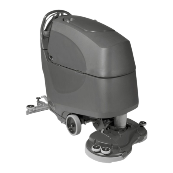
TGB 2228 /8572
B AT T E RY S C R U B B E R D RY E R
Owner Instructions
Warning! Read instructions before using the machine
www.numatic.co.uk
Table of
Contents
Previous
Page
Next
Page
1
2
3
4
5
Advertisement
Table of Contents
Need help?
Do you have a question about the TGB 2228 and is the answer not in the manual?
Ask a question
Questions and answers
Related Manuals for Numatic TGB 2228
Scrubber Numatic HGB 3045 Original Instructions Manual
Battery scrubber dryer (60 pages)
Scrubber Numatic HGB 817 Owner's Instructions Manual
Scrubber dryer (24 pages)
Scrubber Numatic TGB1620T Owner's Instructions Manual
Battery scrubber dryer (24 pages)
Scrubber Numatic TGB2120 Owner's Instructions Manual
Ride-on scrubber dryer (28 pages)
Scrubber Numatic TGB 6055 Original Instructions Manual
Battery scrubber dryer (56 pages)
Scrubber Numatic TGB 8572/200T Owner's Instructions Manual
Battery scrubber dryer (24 pages)
Scrubber Numatic TGB 6055/100 Owner's Instructions Manual
Battery scrubber dryer (28 pages)
Scrubber Numatic TGB 6055/100T Manual
Battery scrubber dryer (56 pages)
Scrubber Numatic HGB 3045/55 Owner's Instructions Manual
Scrubber dryer (32 pages)
Scrubber Numatic HBG 3045/55 Original Instructions Manual
Battery scrubber dryer (60 pages)
Scrubber Numatic TGB 516 Owner's Instructions Manual
Scrubber dryer (20 pages)
Scrubber Numatic TGB 516NX Owner's Instructions Manual
24 volt scrubber dryer (20 pages)
Scrubber Numatic TGB 8572 Owner's Instructions Manual
Battery scrubber dryer (24 pages)
Scrubber Numatic TT 6650S Owner's Instructions Manual
Scrubber dryer (24 pages)
Scrubber Numatic TT 1840G Original Instructions Manual
Scrubber dryer (45 pages)
Scrubber Numatic TVL850/150 Original Instructions Manual
Ride-on scrubber dryer (208 pages)
This manual is also suitable for:
Tgb 8572
906604
Table of Contents
Print
Rename the bookmark
Delete bookmark?
Delete from my manuals?
Login
Sign In
OR
Sign in with Facebook
Sign in with Google
Upload manual
Upload from disk
Upload from URL


Need help?
Do you have a question about the TGB 2228 and is the answer not in the manual?
Questions and answers