Table of Contents
Advertisement
Quick Links
FASSTest12CH(Telemetry OFF)mode
This mode is forcibly turning o昀昀 telemetry transmission to prevent
collision of telemetry signals from the receiver to the transmitter
when using dual RX link mode in FASSTest12ch mode.
1
Turn on the receiver. [Transmitter is always OFF]
2
Press and hold the SW for 5 seconds or more.
Blinking switches every 5 seconds as follows.
RED ⇒ ORANGE ⇒ GREEN ⇒ ORANGE slow blink
3
Release the
switch here
Blinks ORANGE once
FASSTest12CH(Telemetry
OFF)mode : OFF
Press SW once more
to return to flashing
4
orange once
Press switch
Blinks ORANGE twice
FASSTest12CH(Telemetry
OFF)mode : ON
5
Press and hold the SW
Blinks ORANGE
C h a n g e t o t h i s
C h a n g e t o t h i s
6
mode when using
mode when using
Release SW
FASSTest12CH in
FASSTest12CH in
dual RX link mode.
dual RX link mode.
Solid ORANGE
7
Turn off the receiver power
After restarting, the
LINK LED lights up.
In FASSTest12CH Telemetry OFF Mode
Status
LINK LED
Start
Orange Solid
Hobby Radio Control Business Center Sales & Marketing Department
1080 Yabutsuka, Chosei-mura, Chosei-gun, Chiba-ken, 299-4395, Japan TEL: +81-475-32-6051, FAX: +81-475-32-2915
How to Dual Rx Link
1
Install two receivers on the aircraft as shown in the
2
Link the two receivers using the dual receiver feature
of the transmitter.
For systems without dual receiver capability, link
each receiver in turn.
Transmitter in link mode
For FASSTest 18CH Select dual mode and link primary
*Follow the link procedure
for each receiver manual.
Transmitter in link mode
For FASSTest 18CH Select dual
mode and link secondary
◆ About telemetry system
When using the dual receiver function
・The telemetry function of the main receiver can be used
・Sub-receiver telemetry function is not available
Telemetry for FASSTest12CH
In FASSTest12CH mode, after linking R7208SB in telemetry
OFF mode, link the receiver you want telemetry to. (The
transmitter will show the telemetry of the last linked transmitter.)
#1
First Link
Telemetry OFF
mode
#2
Second Link
Telemetry
#1
Telemetry OFF
First Link
mode
e.g.
#2
Second Link
FASSTest receiver
Telemetry
#2
Telemetry display of second-linked receiver.
#1
Telemetry OFF first-Linked receiver.
Compliance Information Statement (for U.S.A.)
This device, trade name Futaba Corporation, model number R7208SB, complies with part15 of the FCC
Rules. Operation is subject to the following two conditions:
(1) This device may not cause harmful interference, and
(2) This device must accept any interference received, including interference that may cause undesired operation.
CAUTION: To assure continued FCC compliance
1. Any changes or modi昀椀cations not expressly approved by the grantee of this device could void the user's
authority to operate the equipment.
2. This equipment complies with FCC radiation exposure limits set forth for an uncontrolled environment.
This equipment should be installed and operated with minimum distance 20cm between the radiator & your body.
The responsible party of this device compliance is:
FUTABA Corporation of America 2681 Wall Triana Hwy Huntsville, AL 35824, U.S.A.
Phone:1-256-461-9399 FAX:1-256-461-1059 E-mail: service@futabaUSA.com
FUTABA CORPORATION
©FUTABA CORPORATION
1M23N38308
R7208SB
◆ FASSTest-2.4GHz Bidirectional Communication System
◆ Dual Rx Link System Equipment
◆ S.BUS2 / S.BUS Port and 8 Channels for Conventional System
Receiver
● Applicable systems: Futaba FASSTest-2.4GHz system transmitter
Usage precaution
Turn on the main
receiver and link
• Analog servos cannot be used with the R7208SB in the FASSTest
12CH mode.
• Don't connect to Extra Voltage before turning on a receiver.
WARNING
Changes or modification not approved by the party responsible for
compliance could void the user's authority to operate the equipment.
The R7208SB receiver should be protected from vibration by foam
rubber, Velcro, or similar mounting methods. Protect from moisture.
Keep away from conductive materials to avoid short circuits.
Turn on the sub
Antenna installation precaution
receiver and link
Do not cut or bundle the receiver antenna wire.
The antennas must be mounted in such a way to assure they are strain
relieved.
Keep the antenna as far away from the motor, ESC and other noise
sources as you possibly can.
Do not touch the antenna to metal, carbon, or other conductive
material.
Be sure that the two antennas are placed at 90 degrees to each other.
■ The R7208SB has two antennas. In order to maximize signal reception
and promote safe modeling Futaba has adopted a diversity antenna system.
This allows the receiver to obtain RF signals on both antennas and fly
problem-free.
(Typical installation)
#2
Display
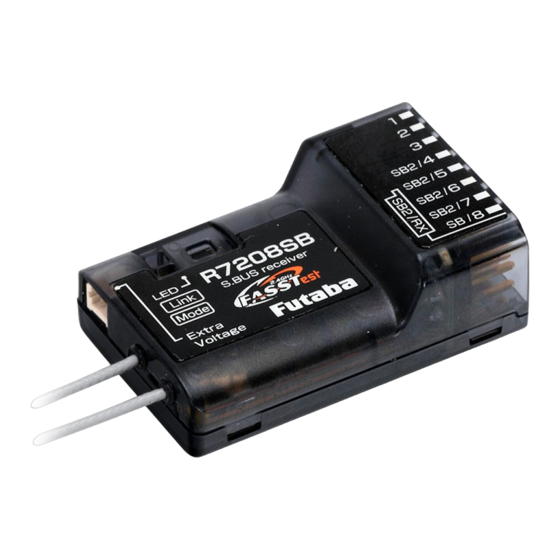
The R7208SB
The
R7208SB has a port switching
has a port switching
function. If SB2/4
SB2/4 to to SB2/7
SB2/7 ports are also
function. If
set to S.BUS2, sensors can be connected.
set to S.BUS2, sensors can be connected.
Extra Voltage Port
#2
It connects with the battery
Display
for power, etc.
E x t er n a l vo l t a g e i np u t
cable of an option is used.
The voltage of the battery
can be displayed with a
transmitter.
R7208SB Specifications
FASSTest-2.4 GHz system(18 ch/12 ch mode)
S.BUS2 and S.BUS port and 8 channels for conventional system receiver
• Dual antenna diversity
• Size: 0.98 x 1.53 x 0.56 in. (24.9 x 38.8 x 14.3 mm)
• Weight: 0.35 oz. (9.9 g)
• Power requirement: 3.7 V to 7.4 V(Voltage range: 3.5 V to 8.4 V)
• Battery F/S Voltage: It sets up with a transmitter
• Extra Voltage port: 0 ~ 70 V DC
2022, 12 (1)
Thank you for purchasing a Futaba R7208SB
FASSTest-2.4GHz compatible receiver. The
R7208S B r e c e i v e r f e a t u r e s b i - d i r e c t i o n a l
communication with a FASSTest Futaba transmitter
using the S.BUS2 port. Using the S.BUS2 port
an impressive array of telemetry sensors may be
utilized. It also includes both standard PWM
output ports (1-8ch) and S.BUS output ports. The
R7208SB can also be switched to the Dual Rx
Link System. This system can ensure safety by
mounting two FASSTest receivers on one aircraft.
Antenna installation for carbon fuselage
You must leave 30mm at the tip of the antenna fully exposed. The
exposed antenna should be secured so that it cannot move around or
back inside of your aircraft.
Be careful of connector insertion
Don't connect an S.BUS servo / gyro to S.BUS2 connector.
Link precaution
Do not perform the linking procedure while the motor's main power is
connected or the engine is operating as it may result in serious injury.
When the linking is complete, please cycle the receiver power and
ensure the receiver is properly linked to the transmitter.
Power on the system in this order: Transmitter 昀椀rst, followed by the
receiver.
If the R7208SB receiver was previously linked to another transmitter,
make sure that transmitter is not operating while linking the receiver to
the new transmitter.
Connector precaution
Don't connect a connector, as shown in
this 昀椀gure.
■ It will short-circuit, if it connected in this way.
A short circuit across the battery terminals may
cause abnormal heating, fire and burns.
When all ports are used.
HUB
Servo
ports are also
Battery
Switch
3.7 ~ 7.4 V
A battery is connectable
also with which port.
Mode LED
Link LED
R7208SB
Antenna
S.BUS2 port
Mode switch
(S.BUS2)
(It is not used for a link.)
*Be sure that when using ESCs regulated
output the capacity of the ESC must meet
your usage condition.
*Never use dry batteries for the power sup-
ply of the R7208SB as they may cause
di昀케culties.
Percentage of Waste
Paper pulp 80%
DANGER
Receiver
Do not insert either a switch
or battery in this manner.
Servo for conventional
system
S.BUS Servo
S.BUS Gyro
Channel 1 output
Channel 8 output
HUB
S.BUS port
(8/SB)
Temperature
Sensor
Voltage
Sensor
HUB
Current
Sensor
RPM
Sensor
HUB
HUB
Altitude
Sensor
Airspeed
Sensor
HUB
S.BUS2 Tool
Advertisement
Table of Contents

Related Manuals for FUTABA R7208SB


Summary of Contents for FUTABA R7208SB
- Page 1 Sensor Compliance Information Statement (for U.S.A.) (It is not used for a link.) This device, trade name Futaba Corporation, model number R7208SB, complies with part15 of the FCC After restarting, the R7208SB Specifications Rules. Operation is subject to the following two conditions:...
- Page 2 The LED will flash for the current CH Current CH mode aux rayonnements IC établies pour un environnement non contrôlé. Hereby, Futaba Corporation declares that the radio equipment type is R7208SB in compliance with Directive S.BUS signal reception from external receiver display Cet équipement est conforme aux limites d’exposition aux rayonnements IC établies pour un environnement...
Need help?
Do you have a question about the R7208SB and is the answer not in the manual?
Questions and answers