Bosch B942W, B942 - Touch Screen Keypad Installation Manual
- User quick reference manual (2 pages) ,
- Installation manual (2 pages) ,
- Installation manual (2 pages)
Advertisement
- 1 Overview
- 2 Touch screen keypad
- 3 Install the mounting plate
- 4 Wire the keypad
- 5 Set the address
- 6 Status indicators
- 7 Audible tones
- 8 Supervision
- 9 Proximity reader
- 10 Addresses, points, and output numbers
- 11 Configure Emergency Key functions
- 12 Firmware updates
- 13 Keypad cleaning
- 14 Specifications
- 15 Documents / Resources
Overview
The B942/B942W Touch Screen Keypad is an SDI2 compatible device. The keypad has user adjustable options such as volume and screen brightness, and has a display that shows color graphics. The B942 keypad connects to the SDI2 bus on the control panel. You can connect more than one keypad to the control panel by wiring them in parallel.
You can program, diagnose, and troubleshoot the system from the keypad as well as remotely through Remote Programming Software (RPS).
The keypad provides four inputs and one output.
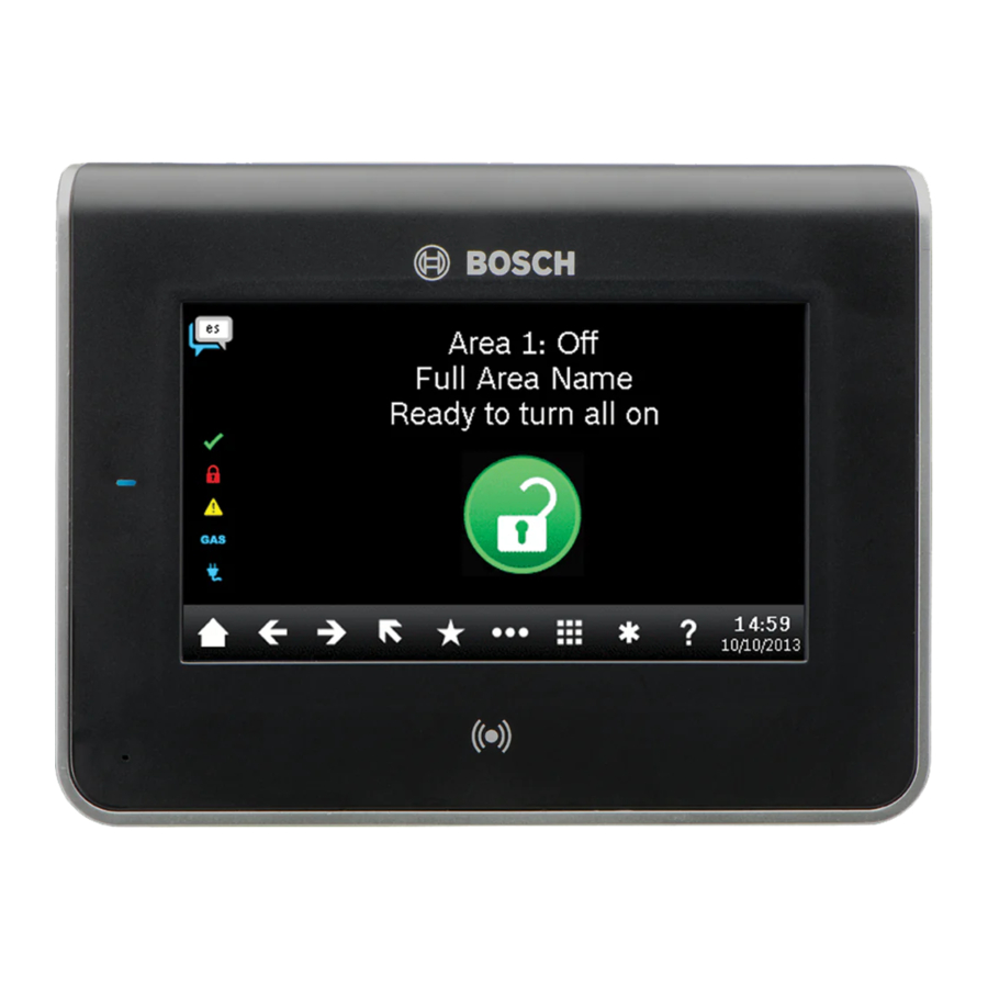
Touch screen keypad

Figure 1.1: Touch screen keypad
Callout ― Description
- Power indicator LED (shows even when screen dims)
- Integrated proximity reader (for use with RF ID token and access cards)
- Presence sensor
Install the mounting plate
To install the keypad mounting plate, fi rst remove the plate from the back of the keypad.
Remove the mounting plate
Removing the mounting plate from the keypad (Figure 2.1):
- Insert a slotted screwdriver under the retention clip to release the clip. Do not pry upwards or twist.
- With your other hand, slide the mounting plate towards the bottom of the keypad to unhook the mounting plate from the keypad.

Figure 2.1: Removing the keypad from base
Mount the mounting plate
Choose the fl ush mounting plate (Figure 2.2 left side) for fl ush mounting, or the surface mounting plate (Figure 2.3 right side) for surface mounting.
Mounting the plate on the wall:
- The surface plate includes a bubble level. Use the plate as a template to mark the desired mounting surface with mounting locations. Refer to Figure 2.2 for mounting hole locations.
- Pull the wiring through the desired wire opening.
- Use the appropriate mounting hardware (supplied) to attach the mounting plate to the mounting surface.

Figure 2.2: Mounting the plate
Wire the keypad
Prior to placing the keypad on the mounting plate, wire the keypad to the control panel, and to any inputs and any output, as desired. The terminal block for wiring is clearly marked.

Remove all power (AC and battery) before making any connections. Failure to do so might result in personal injury and/or equipment damage.
 NOTICE! Do not use a screwdriver on the terminals. Use a ballpoint pen instead to avoid permanent damage to the terminals.
")
Figure 3.1: Keypad back (with mounting plate removed)
NOTICE! Use the strip gauge on the mounting plate to strip the wires to 7 mm. Only one (1) wire per terminal.
Place the keypad on a smooth surface when wiring.
To insert wires into the terminals, use a ballpoint pen to press the button on the terminal release, and with the other hand, push the wire into the terminal. (Refer to Figure 3.2.) When you remove the pen, the terminal release locks in the wire. To remove wires, press the terminal release, push the wire gently, and then pull the wire out.

Figure 3.2: Inserting wire into the terminals
Wire to the control panel
When you wire the keypad to a control panel, use the control panel terminals labeled R, Y, G, B (PWR, A, B, COM). Connect them to the keypad terminals labeled R, Y, G, B (PWR, A, B, COM). Refer to Figure 3.3.
You can connect keypads to the SDI2 data bus by parallel wire run from the control panel to each keypad, wire from keypad to keypad, or a combination of the two techniques. Refer to Figure 3.4.

Figure 3.3: Wiring the keypad to the SDI2 bus connection
(B5512 shown)
Callout ― Description
- Control panel
- Terminal wiring
- Keypad's wiring terminal block
")
Figure 3.4: Installing multiple keypads using the SDI2 terminals (B5512 shown)
Wire the inputs
Wire resistance on each sensor input must be less than 100 Ω with the detection devices connected. The terminal block supports 18 to 22 AWG (1.02 to 0.65 mm) wires.
The keypad detects open, short, normal, and ground fault circuit conditions on its sensor loops and transmits the conditions to the control panel. Each sensor loop is assigned a point number and transmits to the control panel individually. Run wires away from the premises telephone and AC wiring.

Figure 3.5: Installing sensor loop wiring
Callout ― Description
- Keypad terminal strip
- Keypad sensor loops
- 1 kΩ EOL resistor (ICP-1K22AWG-10)
Wire the output
The keypad provides one NO (normally open) output. (It includes NO and C (COMMON) terminals.) When the output is in an active (energized) state, the NO has continuity with the C terminal.
NOTICE! Do not exceed relay contact ratings of 1.0 A, 24 VDC, resistive load.
Mount the keypad
After wiring the keypad, mount the keypad onto the mounting plate by seating the mounting hook openings over the mounting hooks and then sliding the keypad down.
Set the address
Use the steps below to set the address for the keypad. If multiple SDI2 keypads reside on the same system, each SDI2 keypad must have a unique address. For single-digit addresses 1 through 9, set the tens switch to 0. Figure 4.1 shows the address switch setting for address 1.

Figure 4.1 Keypad addressing page
NOTICE! Only use your fi nger or a stylus intended for touch screens to operate the keypad.
Setting the keypad address:
- When you apply power to the keypad, the start up screen shows. You can also show the startup screen by pressing and holding the Time/ Date in the ribbon bar for 5 seconds, or by pressing and holding anywhere on the Call for Service screen. Press screen hold the countdown icon for 5 seconds. The keypad addressing page shows.
- To set the address, use the up and down arrows on the right of the switches image to change the ones digit, and the arrows on the left to change the tens digit.
- Press the
![]() (escape) icon to save the setting and return to the power up screen.
(escape) icon to save the setting and return to the power up screen.
 (escape) icon to save the setting and return to the power up screen.
Status indicators
You can diagnose and troubleshoot the system using the keypad's status indicators. Refer to Table 5.1.
| Status icon | Function |
 | Green check - Ready to turn on (arm) |
 | Red lock - Turned on (armed) |
| | Yellow caution - System trouble |
 | Blue GAS - Gas alarm |
 | Blue plug - AC power present |
Table 5.1: Keypad status icons
Audible tones
The keypad has a built-in speaker that produces several distinct warning tones. The keypad backlight illuminates when it emits an audible tone.
| Tone | Description |
| Fire signal | When an area is in fi re alarm, the keypad emits a pulsed, high-pitched bell tone. |
| Gas signal | When a gas point activates, the keypad emits a unique high pitched tone. |
| User alarm | When a user alarm (such as panic and medical alarms) occurs, the tone sounds for the programmed amount of time. |
| Burglary signal | When an area is in alarm, the keypad emits a steady, high pitched bell tone. |
| Entrance warning | The keypad emits an intermittent beep tone during entry delay periods to remind the user to disarm the area. |
| Exit warning | The keypad emits an intermittent beep tone during exit delay. |
| Invalid button buzz | When an invalid button, or sequence of buttons, is pressed, the keypad emits a fl at buzz tone. |
| Keypad encoding tone | The keypad emits a muted beep tone as each button is pressed to indicate that the entry was accepted. |
| Trouble buzzer | When a trouble event occurs, such as a service alert, the keypad emits a two-tone warble until you enter a programmed passcode with the appropriate authority. |
| Watch tone | A single clean tweedle tone alerts the user anytime a watch point is faulted. |
Table 6.1: Keypad audible tones
Supervision
The control panel supervises all keypads on the SDI2 bus.
If a keypad fails to respond to the control panel, the control panel declares a Missing Keypad Trouble. When the control panel can again communicate with the keypad, it restores the Missing Keypad Trouble.
During a Missing Keypad Trouble, any connected keypad that maintained contact with the control panel shows the Missing Keypad Trouble as its idle text, and shows the missing keypad's address. The communicating keypads also sound a trouble tone. Users can silence the trouble tone. If no other troubles exist, the tone silences when the missing keypad restores.
Proximity reader
The proximity reader allows users to use a token or card in place of a passcode to turn on or off the security system. The proximity reader supports EM4102 (125 kHz) credentials. The Bosch ACA-ATR13-RFID tag and Bosch ACD-ATR11ISO-RFID card are examples.
Addresses, points, and output numbers
To determine the point numbers or output number for each keypad address, multiply the address number by 10 for the base number, and then use numbers 1 through 4 in the ones place for the point numbers. Use 1 in the ones place for the output number.
Examples
For keypad address 01 the point numbers for the input devices are 11 through 14:
| Terminal no | 1 | 2 | 3 | 4 |
| Input no | 11 | 12 | 13 | 14 |
For output devices connected to the NO and C terminals the output number is 11.
For keypad address 03 the point numbers for the input devices are 81 through 34:
| Terminal no | 1 | 2 | 3 | 4 |
| Input no | 31 | 32 | 33 | 34 |
For output devices connected to the NO and C terminals the output number is 31.
Configure Emergency Key functions
To enable the Emergency Key functions use RPS to set the A,B,C Key Response parameters (KEYPADS/Global Keypad Settings) as follows:
- To enable the Fire key, set A Key Response to Manual fi re alarm.
- To enable the Medical key, set B Key Response to Manual medical alarm (with or without alarm bell).
- To enable the Panic key, set C Key Response to Manual panic alarm (invisible or visible).
Firmware updates
Firmware updates require a MicroSD card (2 GB to 32 GB).
Updating the keypad firmware:
- Go to the Bosch website (us.boschsecurity.com) and download the firmware from the B942 product page.
- Save the firmware to your MicroSD card.
- Ensure the keypad is powered.
- Slide the MicroSD card into the MicroSD card slot until it clicks into place. Refer to Figure 11.1.
- The keypad power indicator LED fl ashes during the update. The keypad also shows Please wait while programming fl ash.
- If the keypad shows the calibration screen, follow the on-screen instructions to calibrate.
- When the update completes, the keypad shows Firmware update successful. Remove SD card to continue.
- Remove the memory card from the device. To do so, press down on the card and quickly remove pressure. The card clicks out of place. Use your fi ngernail on the upper groove on the card to slide it out.
- The keypad shows the power up screen with the updated revision number and then shows the Home screen.

Figure 11.1: Inserting a MicroSD card
Keypad cleaning
Use a soft cloth and non-abrasive cleaning solution to clean your keypad (for example, microfi ber cloth and eyeglass cleaner). Spray the cleaner onto the cloth. Do not spray cleaners directly onto the keypad.
Specifications
| Dimensions | 6.2 in x 4.7 in x 0.6 in (158 mm x 120 mm x 16 mm) |
| Voltage (input) | 12 VDC nominal |
| Current with prox detection disabled | 200 mA in standby mode 300 mA in alarm mode |
| Current with prox detection enabled | 300 mA in standby mode 400 mA in alarm mode |
| Operating temperature | 0°C to +50°C (+32°F to +122°F) |
| Relative humidity | 5% to 93% at +32°C (+90°F) noncondensing |
| Terminal wire size | 18 AWG to 22 AWG (1.02 mm to 0.65 mm) |
| SDI2 wiring with prox detector disabled | Maximum distance - wire size (unshielded wire only): 200 ft (61 m) - 22 AWG (0.65 mm) 520 ft (159 m) - 18 AWG (1.02 mm) |
| SDI2 wiring with prox detector enabled | Maximum distance - wire size (unshielded wire only): 150 ft (46 m) - 22 AWG (0.65 mm) 390 ft (119 m) - 18 AWG (1.02 mm) |
| Compatibility | B5512/B5512E firmware v2.03 and higher B4512/B4512E firmware v2.03 and higher B3512/B3512E firmware v2.03 and higher D9412GV4 firmware v2.03 and higher D7412GV4 firmware v2.03 and higher |
Copyright
This document is the intellectual property of Bosch Security Systems, Inc. and is protected by copyright. All rights reserved.
Trademarks
All hardware and software product names used in this document are likely to be registered trademarks and must be treated accordingly.
Bosch Security Systems, Inc. product manufacturing dates

Use the serial number located on the product label and refer to the Bosch Security Systems, Inc. website at http://www.boschsecurity.com/datecodes/.

Documents / Resources
References
Download manual
Here you can download full pdf version of manual, it may contain additional safety instructions, warranty information, FCC rules, etc.
Download Bosch B942W, B942 - Touch Screen Keypad Installation Manual
Advertisement


Need help?
Do you have a question about the B942W and is the answer not in the manual?
Questions and answers