Bosch B942 Installation Manual
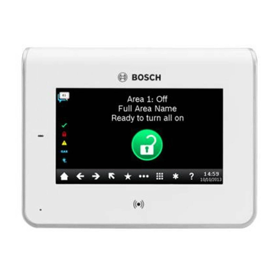
Touch screen keypad
Hide thumbs
Also See for B942:
- Installation manual ,
- User quick reference manual (2 pages) ,
- Installation manual (2 pages)
Advertisement
Quick Links
1 | Overview
The B942/B942W Touch Screen Keypad is an SDI2 compatible
device. The keypad has user adjustable options such as volume and
screen brightness, and has a display that shows color graphics. The
B942 keypad connects to the SDI2 bus on the control panel. You can
connect more than one keypad to the control panel by wiring them
in parallel.
You can program, diagnose, and troubleshoot the system from
the keypad as well as remotely through Remote Programming Software
(RPS).
The keypad provides four inputs and one output.
Figure 1.1: Touch screen keypad
Callout ― Description
1 ― Power indicator LED (shows even when screen dims)
2 ― Integrated proximity reader (for use with RF ID token and
access cards)
3 ― Presence sensor
2 | Install the mounting plate
To install the keypad mounting plate, fi rst remove the plate from the
back of the keypad.
2.1 | Remove the mounting plate
Removing the mounting plate from the keypad:
1.
Insert a slotted screwdriver under the retention clip to release
the clip. Do not pry upwards or twist. Refer to Figure 2.1.
2.
With your other hand, slide the mounting plate towards the
bottom of the keypad to unhook the mounting plate from the
keypad. Refer to Figure 2.1.
Figure 2.1: Removing the keypad from base
2.2 | Mount the mounting plate
Choose the fl ush mounting plate (Figure 2.2 left side) for fl ush
mounting, or the surface mounting plate (Figure 2.3 right side) for
surface mounting.
Mounting the plate on the wall:
1.
The surface plate includes a bubble level. Use the plate as a
template to mark the desired mounting surface with mounting
locations. Refer to Figure 2.2 for mounting hole locations.
2.
Pull the wiring through the desired wire opening.
3.
Use the appropriate mounting hardware (supplied) to attach the
mounting plate to the mounting surface.
Figure 2.2: Mounting the plate
3 | Wire the keypad
Prior to placing the keypad on the mounting plate, wire the keypad to
the control panel, and to any inputs and any output, as desired. The
terminal block for wiring is clearly marked.
CAUTION!
Remove all power (AC and battery) before making any
connections. Failure to do so might result in personal injury
and/or equipment damage.
NOTICE!
Do not use a screwdriver on the terminals. Use a ballpoint
pen instead to avoid permanent damage to the terminals.
R
Y
G
B
1 COM 2 COM 3 COM 4 COM NO C
PWR A
B COM
R
Y
G
B
1 COM 2 COM 3 COM 4 COM NO C
PWR A
B COM
Figure 3.1: Keypad back (with mounting plate removed)
NOTICE!
Use the strip gauge on the mounting plate to strip the
wires to 7 mm. Only one (1) wire per terminal.
Place the keypad on a smooth surface when wiring.
To insert wires into the terminals, use a ballpoint pen to press the
button on the terminal release, and with the other hand, push the wire
into the terminal. (Refer to Figure 3.2.) When you remove the pen, the
terminal release locks in the wire. To remove wires, press the terminal
release, push the wire gently, and then pull the wire out.
Figure 3.2: Inserting wire into the terminals
3.1 | Wire to the control panel
When you wire the keypad to a control panel, use the control panel
terminals labeled R, Y, G, B (PWR, A, B, COM). Connect them to the
keypad terminals labeled R, Y, G, B (PWR, A, B, COM).
Refer to Figure 3.3.
You can connect keypads to the SDI2 data bus by parallel wire run from
the control panel to each keypad, wire from keypad to keypad, or a
combination of the two techniques. Refer to Figure 3.4.
R Y G B
Open
3.7 - 5.0 VDC
Normal
2.0 - 3.0 VDC
Short
0.0 - 13 VDC
1 k
End of Line Resistors
1
AUX
- 12 V +
1 COM 2
3 COM 4
5 COM 6
3
COM AUX
R
Y
G
B
1
COM
2
3
COM
PWR A
B COM
R Y G B
R
Y
G
B
2
1 COM 2 COM 3 COM 4 COM NO C
PWR A
B COM
R
Y
G
B
1 COM 2 COM 3 COM 4 COM NO C
PWR A
B COM
Figure 3.3: Wiring the keypad to the SDI2 bus connection
(B5512 shown)
Callout ― Description
1 ― Control panel
2 ― Terminal wiring
3 ― Keypad's wiring terminal block
R Y G B
Open
3.7 - 5.0 VDC
Normal
2.0 - 3.0 VDC
Short
0.0 - 13 VDC
1 k
End of Line Resistors
AUX
- 12 V +
1 COM 2
3 COM 4
5 COM 6
COM AUX
R
Y
G
B
1
COM
2
3
COM
PWR A
B COM
R Y G B
R
Y
G
B
R
Y
G
B
1 COM 2 COM 3 COM 4 COM NO C
1 COM 2 COM 3 COM 4 COM NO C
PWR A
B COM
PWR A
B COM
R
Y
G
B
R
Y
G
B
1 COM 2 COM 3 COM 4 COM NO C
1 COM 2 COM 3 COM 4 COM NO C
PWR A
B COM
PWR A
B COM
R
Y
G
B
3.2 | Wire the inputs
Wire resistance on each sensor input must be less than
100 Ω with the detection devices connected. The terminal block
supports 18 to 22 AWG (1.02 to 0.65 mm) wires.
The keypad detects open, short, normal, and ground fault circuit
conditions on its sensor loops and transmits the conditions to the
control panel. Each sensor loop is assigned a point number and
transmits to the control panel individually. Run wires away from the
premises telephone and AC wiring.
R
Y
G
B
1 COM 2 COM 3 COM 4 COM NO C
PWR A
B COM
Figure 3.5: Installing sensor loop wiring
Callout ― Description
1 ― Keypad terminal strip
2 ― Keypad sensor loops
3 ― 1 kΩ EOL resistor (ICP-1K22AWG-10)
3.3 | Wire the output
The keypad provides one NO (normally open) output. (It includes
NO and C (COMMON) terminals.) When the output is in an active
(energized) state, the NO has continuity with the C terminal.
NOTICE!
Do not exceed relay contact ratings of 1.0 A, 24 VDC,
resistive load.
3.4 | Mount the keypad
After wiring the keypad, mount the keypad onto the mounting plate
by seating the mounting hook openings over the mounting hooks
and then sliding the keypad down.
4 | Set the address
Use the steps below to set the address for the keypad. If multiple
SDI2 keypads reside on the same system, each SDI2 keypad must
have a unique address. For single-digit addresses 1 through 9, set
the tens switch to 0.
Figure 4.1 shows the address switch setting for address 1.
NOTICE!
Only use your fi nger or a stylus intended for touch screens
to operate the keypad.
Setting the keypad address:
1.
When you apply power to the keypad, the start up screen shows. You
can also show the startup screen by pressing and holding the Time/
Date in the ribbon bar for 5 seconds, or by pressing and holding
anywhere on the Call for Service screen. Press screen hold the
countdown icon for 5 seconds. The keypad addressing page shows.
2.
To set the address, use the up and down arrows on the right of the
switches image to change the ones digit, and the arrows on the left
to change the tens digit.
3.
Press the (escape) icon to save the setting and return to the
power up screen.
Figure 4.1: Keypad addressing page
Advertisement

Related Manuals for Bosch B942


Summary of Contents for Bosch B942
- Page 1 1 COM 2 COM 3 COM 4 COM NO C PWR A B COM B942 keypad connects to the SDI2 bus on the control panel. You can Mounting the plate on the wall: Refer to Figure 3.3. connect more than one keypad to the control panel by wiring them The surface plate includes a bubble level.
- Page 2 Users can silence Copyright the trouble tone. If no other troubles exist, the tone silences when This document is the intellectual property of Bosch Security Systems, Inc. Figure 11.1: Inserting a MicroSD card the missing keypad restores.
Need help?
Do you have a question about the B942 and is the answer not in the manual?
Questions and answers