Bosch B920 Installation Manual
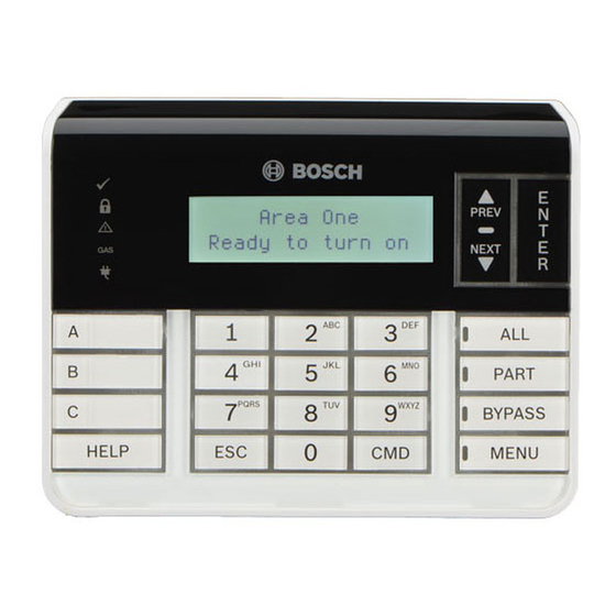
Two-line alphanumeric keypad
Hide thumbs
Also See for B920:
- Installation manual ,
- Quick start manual (3 pages) ,
- User quick reference manual (2 pages)
Table of Contents
Advertisement
Quick Links
1 | Overview
This keypad is SDI2 compatible. Multiple keypads can be
connected to the control panel by wiring them in parallel.
1
3
6
2
1
10
4
7
7
5
R Y G B
6
1
2
3
6
5
Callout ― Description
1 ― Wall mount holes
2 ― Single gang box holes
3 ― Double gang box holes
4 ― Wire opening
5 ― Surface mount wire openings
6 ― Gang box holes (3-4 in)
7 ― Surface mount wire channel
8 ― Bubble level
9 ― SDI2 wiring terminal block
10 ― Wire tie posts
2 | SDI2 address switches
Two switches determine the address for the keypad. The control
panel uses the address for communications. To set the switches,
use a slotted screwdriver.
2.1 | Access the address switches
1.
Use a slotted screwdriver. Turn the lock counter-
clockwise.
2.
Push down on the keypad to remove it from the base.
3.
Find the switches on the back of the keypad.
Refer to the following illustrations.
10
5
9
10
8
1
Callout ― Description
1 ― Address switches
2.2 | Setting the address switches
Set the address switches per the control panel configuration.
If multiple SDI2 keypads reside on the same system, each
SDI2 keypad must have a unique address. For single-digit
addresses 1 through 9, set the tens switch to 0. The following
illustration shows the address switch setting for address 1.
.
3 | Installing
Caution!
Remove all power (AC and battery) before making any
connections. Failure to do so might result in personal
injury and/or equipment damage.
3.1 | Installing the keypad
You can surface install the keypad, or install it to standard
electrical boxes, including single gang boxes.
1.
Use the base as a template to mark surface.
2.
Pull the wiring through the opening in the base.
3.
Use the mounting hardware to attach.
3.2 | Attaching to the control panel
Use the control panel terminals labeled R, Y, G, B (PWR, A, B,
COM). Connect them to the keypad terminals labeled R, Y, G, B.
Keypads can be wired directly to the control panel or from
keypad to keypad.
Callout ― Description
1 ― Control panel
2 ― Terminal wiring
3 ― Keypad's wiring terminal block
Reconnect the keypad to the base by sliding the keypad onto
the base (reverse of Step 2). Apply power to the system.
4 | Display
Adjusting brightness:
1.
Push [MENU] to open.
2.
Push [NEXT] to go to the Press 5 for Settings Menu option,
or press [5].
3.
Push [NEXT] to go to the Press 4 for Keypad Config option,
or press [4].
4.
Push [1] to adjust the brightness.
5.
Push [PREV] or [NEXT] to adjust the brightness. The
changes apply immediately.
6.
Push [ESC] to exit.
Adjusting nightlight (for control panels with version 2.01 or
higher):
1.
Push [MENU] to open.
2.
Push [NEXT] to go to the Press 5 for Settings Menu option,
or press [5].
3.
Push [NEXT] to go to the Press 4 for Keypad Config option,
or press [4].
4.
Push [NEXT] to go to the Press 4 for Nightlight option, or
press [4].
5.
Push [PREV] or [NEXT] to toggle between Yes and No.
6.
Push [ENTER] while viewing the option to save the
programming.
7.
Push [ESC] to exit.
Advertisement
Table of Contents

Related Manuals for Bosch B920


Summary of Contents for Bosch B920
- Page 1 1 | Overview 2.1 | Access the address switches 3 | Installing This keypad is SDI2 compatible. Multiple keypads can be Use a slotted screwdriver. Turn the lock counter- Caution! connected to the control panel by wiring them in parallel. clockwise.
- Page 2 ULC-ORD C1076 - Proprietary Burglar Alarm Units and Systems ICES-003 - Digital Apparatus Copyright This document is the intellectual property of Bosch Security Systems, Inc. and is protected by copyright. All rights reserved. Bosch Security Systems, Inc. Bosch Sicherheitssysteme GmbH...
Need help?
Do you have a question about the B920 and is the answer not in the manual?
Questions and answers