Table of Contents
Advertisement
Quick Links
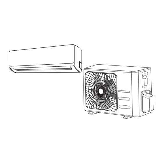
Single-Zone Mini-Split Systems
4DHV Outdoor Units and DWH Indoor Units
This is a safety alert symbol and should never be ignored. When you see this symbol on labels or in manuals, be alert to
the potential for personal injury or death.
WARNING
Improper installation, adjustment, alteration, ser vice
or maintenance can cause property damage, personal
injury or loss of life.
Installation and service must be performed by a li-
censed professional HVAC installer (or equivalent) or a
service agency.
CAUTION
As with any mechanical equipment, contact with sharp
sheet metal edges can result in personal injury. Take
care while handling this equipment and wear gloves
and protective clothing.
Manufactured By
Allied Air Enterprises LLC
A Lennox International, Inc. Company
215 Metropolitan Drive
West Columbia, SC 29170
507949-01
USER'S INFORMATION MANUAL
This manual must be left with the homeowner for future reference.
General
This wall-mounted indoor unit is matched with an outdoor
heat pump unit to create a mini-split system that uses
HFC-410A refrigerant.
Optimal Performance
Optimal performance for the COOL and DRY modes can
be achieved in the following temperature ranges. When
your heat pump is used outside of these ranges, certain
safety protection features will activate and cause the unit
to perform less than optimally.
Temperature
Location
Room
Outdoor
Table 1. Cool and Dry Mode Optimal
To further optimize the performance of your unit, do the
following:
•
Keep doors and windows closed.
•
Limit energy usage by using TIMER ON and TIMER
OFF functions.
•
Do not block air inlets or outlets.
•
Regularly inspect and clean air filters.
*P507949-01*
Issue 2011
Cool or Dry
Modes
62°F - 90°F
(17°C - 32°C)
5°F - 122°F
(-15°C - 50°C)
(-15°C - 30°C)
Performance Ranges
(P) 507949-01
Heat Mode
32°F - 86°F
(0°C - 30°C)
5°F - 86°F
Page 1 of 8
Advertisement
Table of Contents

Related Manuals for Lennox 4DHV


Summary of Contents for Lennox 4DHV
- Page 1 USER’S INFORMATION MANUAL Single-Zone Mini-Split Systems 4DHV Outdoor Units and DWH Indoor Units This manual must be left with the homeowner for future reference. This is a safety alert symbol and should never be ignored. When you see this symbol on labels or in manuals, be alert to the potential for personal injury or death.
-
Page 2: Unit Parts
Unit Parts Front Panel Wireless Wireless Remote Control Remote Control Holder Louver Return Air Filters (2) ON/OFF SILENCE MODE TIMER TEMP TIMER SLEEP SWING DIRECT TURBO SELF FOLLOW CLEAN Display window “ ” for 3 seconds when: • TIMER ON is set •... -
Page 3: Return Air Filters
Refer to the wireless remote control section on using the Features swing and direct buttons. Return Air Filters Auto Restart If the unit loses power, it will automatically restart with the prior settings once power has been restored. Blocked or dirty return air filters affect system oper ation and efficiency. -
Page 4: Remote Control Specifications
Air Filter Reminders 2. Locate the MANUAL CONTROL button on the right- hand side of the unit. After 240 hours of use, the display window 3. Press the MANUAL CONTROL button to activate on the indoor unit will flash “CL.” This is a FORCED AUTO mode. - Page 5 ON/OFF SILENCE TIMER MODE TEMP TIMER SLEEP SWING DIRECT FOLLOW TURBO SELF CLEAN Figure 5. Remote Controller Function Buttons Timer ON Timer OFF Remote Controller ON Transmitting Signal Display Not Used Battery Charge Status Night Mode Operation Modes Follow Me Not Used Fan Speed Not Used...
-
Page 6: Function Buttons
• Direct (Direction) button. Press to move louvers up Function Buttons and down in six degree increments. Louvers remain in place where stopped. See Figure 5 for illustration for remote function buttons. • LED button. Press the LED button to turn on the •... -
Page 7: Operation Mode
Auto Mode Operation 1. Press the Power button, an LED light on the indoor unit displays. Batteries 2. Press the Mode button until the display shows AUTO. 1. Remove battery cover from back of remote. 3. Adjust temperature setpoint using up and down arrow 2. -
Page 8: Troubleshooting
Troubleshooting FCC Compliance Statement — PART 15.19 If any of the following faults codes appear on your indoor This device complies with Part 15 of the FCC Rules. unit, please contact your li censed professional HVAC Operation is subject to the following two conditions: installer (or equivalent) or a service agency.
Need help?
Do you have a question about the 4DHV and is the answer not in the manual?
Questions and answers