
Related Manuals for SENSIT Technologies SPOD


Summary of Contents for SENSIT Technologies SPOD
- Page 1 OPERATION & CONFIGURATION GUIDE READ AND UNDERSTAND INSTRUCTIONS BEFORE USE. 851 Transport Drive • Valparaiso, IN 46383 (USA) Phone: 219.465.2700 • www.GasLeakSensors.com...
- Page 2 CONTENTS GENERAL IINFORMATION �������������������������������������������������������������������� 3 SENSORS INFORMATION ��������������������������������������������������������������������� 4 CELLULAR SPECIFICATIONS ������������������������������������������������������������������� 5 SENSOR EXTERIOR FEATURES (FRONT EXTERIOR) ���������������������������������� 6 SENSOR INTERIOR FEATURES (FRONT INTERIOR) ����������������������������������� 7 SENSOR INTERIOR LED INDICATION ����������������������������������������������������� 8 QUICK START DEPLOYMENT GUIDE (USB CABLE & COMPUTER) �������������� 9 QUICK START DEPLOYMENT GUIDE (NO COMPUTER) ����������������������������...
- Page 3 GENERAL IINFORMATION OVERVIEW PARAMETER Weight Base Unit: 6.75 lbs Dimensions Fully assembled with anemometer & antenna D x W x H (6” x 8” x 16”) Mounting Attached mounting flanges Voltage Requirements 18V – 24V DC Charging (wired adapter or solar panel) Current Requirements 2A max current draw when charging Operating Runtime...
- Page 4 4. PID Sensors are sensitive to high amounts of humidity and may rail at the upper output if humidity is excessive. The SPOD contains an internal sensor heater to minimize humidity interference. 5. If the unit has been off for an extended period of time, it could take several minutes to an hour for the PID readings to drop to normal operating conditions depending on storage conditions.
- Page 5 CELLULAR SPECIFICATIONS OVERVIEW PARAMETER Network Technology 4G/2G Carrier AT&T and T-mobile Transport Layer Internet Layer Application Layer HTTP and MQTT Data Transfer Method HTTP POST or MQTT Topics HTTP Content Type application/x-www-form-urlencoded HTTP Body Field Identifiers &ID, &MODULE, &STAT, &DATA MQTT Content Type JSON MQTT Tags...
- Page 6 SENSOR EXTERIOR FEATURES (FRONT EXTERIOR)
- Page 7 SENSOR INTERIOR FEATURES (FRONT INTERIOR)
- Page 8 SENSOR INTERIOR LED INDICATION Cellular Status: Red LED if failure, Green LED if successful Charging Status: Green LED if Charging Calibration Mode: Solid/Flashing Blue LED in Calibration Sensor Status: Red LED if initialization failure (PID or Weather Station) SD Card Status: Red LED if failure, Green LED if successful...
- Page 9 7. 1. Install wireless antenna if equipped with cellular or local wireless module. 2. Hook up sample controller if applicable to the auxiliary port of the SPOD using the provided 5 pin cable.
- Page 10 1. Install wireless antenna if equipped with cellular or local wireless module. 2. Hook up sample controller if using to the auxiliary port of the SPOD using the provide 5 pin cable. 3. Power on unit. The illuminated switch should turn on. If the switch does not illuminate, inspect all wiring connections and charge battery.
- Page 11 30-60 seconds and see if the double blink starts again after the cellular post finishes. USB OUTPUT HEADINGS AND DESCRIPTION USB HEADING DESCRIPTION UNITS/FORMAT SPOD Serial Number 1000-63535 DATE Local Date and Time MM/DD/YY HH:MM:SS (24H)
- Page 12 FIELD 1 (PORT STATUS) BIT NUMBER DESCRIPTION 7 (MSB) Port 4: Collected = 1, Not Collected = 0 Port 3: Collected = 1, Not Collected = 0 Port 2: Collected = 1, Not Collected = 0 Port 1: Collected = 1, Not Collected = 0 Port 4: Installed = 1, Not Installed = 0 Port 3: Installed = 1, Not Installed = 0 Port 2: Installed = 1, Not Installed = 0...
- Page 13 ULTRASONIC ANEMOMETER MOUNTING INSTRUCTIONS INSTALLING (FIGURE 3) CAUTION: The reflector plate and the waterproof film found in the wind channel of the WeatherStation Instrument are essential to its operation. Be careful not to scratch the plate, puncture the film, or damage them in any way.
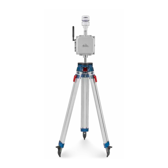
- Page 14 TRIPOD SETUP AND INSTALLATION (OPTIONAL) 1. Remove protective rubber feet if installing outdoors 2. Install pole on tripod. Pole mounting attachment may differ from image below. 3. Set leg height of tripod and spread legs with a minimum of 30° from perpendicular 4.
- Page 15 5. Use the shorter ¼” long screw to attach pole mount to back of SPOD 6. Use the longer 1 ¼” long screw + nut to tighten on pole 7. Tighten sufficiently to prevent rotation 8. Place SPOD as far up as possible on pole to avoid blocking anemometer NOTE: The images below are used for reference.
- Page 16 5. Avoid shadowing on panel as much as possible as this will drastically reduce panel output power and efficiency 6. Route cable to SPOD unit 7. Plug cable into SPOD “Power/USB” connection 8. Power on SPOD unit NOTE: Alternative solar mounts and solar panel extension cables can be purchased from Sensit. Please...
- Page 17 After the correct angle is set, tighten the 4 bolts fully. 5. Avoid shadowing on panel as much as possible as this will drastically reduce panel output power and efficiency 6. Route cable to SPOD unit 7. Plug cable into SPOD “Power/USB” connection 8. Power on SPOD unit...
- Page 18 TRIPOD SETUP & ANCHOR KIT INSTALLATION (OPTIONAL) 1. Adjust tripod to desired height by flipping up red lever and pulling out legs to desired height. The op- timal angle for tripod stability is in the range of 60-65 degrees with respect to the ground 2.
- Page 19 2. Hook any valves and pressure sensors up to the valve/pressure ports. 3. Power on SPOD and configure sampler as described in the USB configuration settings. Please note that when enabling sampling for the first time, the user must power cycle before attempting to configure the sampler parameters.
- Page 20 LED COLOR DESCRIPTION BLUE Not Enabled GREEN Enabled and Not Collected Enabled and Collected RED-GREEN-BLUE Currently Collecting Sample 5. The canister valve controller features 4 local buttons for control and testing. The button behavior will depend on the status of port. When the button is pushed, the LED begins to flash RED-GREEN-RED- GREEN.
- Page 21 7. The connection to the canister is shown here both with and without a pressure sensor and no manifold. The inlet of the valve should be the high pressure (atmosphere) side and the outlet of the valve should be the low pressure (vacuum) side of the valve. 8.
- Page 22 • Computer with a serial port terminal software program (e.g. CoolTerm) SENSOR QUICKSTART INSTRUCTIONS 1. Connect the USB cable to the SPOD and computer and establish the communication link in the termi- nal software. 2. Turn on power switch and observe initialization process. After initializing the micro-controller and printing SPOD information, the system will system will prompt the user to: “Enter Configuration...
- Page 23 DETAILED ROOT MENU INFORMATION CELLULAR: Contains all settings associated with the cellular modem. This is required for communication with any online servers. DEFAULT: Resets all options to the factory default. Not recommended without consulting SENSIT. This will remove all custom settings including cellular information. DISPLAY: Displays all current settings in the terminal window.
- Page 24 “USERPASS” or “AZUREHUB”. To manually configure username and password type “USERPASS”. If using Azure IoT hub, type “AZUREHUB” to send SAS token. The SPOD will parse the relevant connection parameters from the SAS token. The SAS token must have the following parameters to be accepted: SharedAccessSignature sr=<HOSTNAME>%2Fdevices%2F<DEVICEID>...
- Page 25 • “MQTT”: Transfers data using MQTT publish constantly at interval determined by the output data rate (ODR) • “PERIODIC”: Buffers data according to the “RATIO” setting at the output data rate. After the required number of samples has been collected the modem will turn on, post all data, and then turn off. The interval of cellular cycles is determined by “ODR”...
- Page 26 C, D, E, VALUE MEANING Not registered, Not Searching Registered Successfully Not registered, Searching Registration Denied Unknown Status Registered Successfully, Roaming TLS: Enable or disable TLS encryption for HTTPS or MQTTS. For TLS authentication the user must load a root certificate file for the server on the microSD card. Prior to version 6.00 it was necessary to load a certificate file on the SD prior to enabling TLS.
- Page 27 ODR: Sets the output data rate of the cellular modem or XBEE wireless device. The USB port will always show data output at 1Hz POLL: Disable streaming over USB/Port and XBEE. SPOD will return data when receiving any character from control device.
- Page 28 MET: Enable, disable, or turn MET detection to AUTOMATIC. If MET detection fails it is recommended to enter this menu, disable MET, enable MET, and then restart SPOD. This menu also provides the ability customize the MET filter period to smooth out wind data.
- Page 29 This requires a 12V valve and is switched with a 3.3V digital output. Valve must be isolated from SPOD. “NONE” is no sampler hooked up. This should be selected if not using a sampler to avoid and initialization error upon startup. “PRESSURE” is configured to allow the valve controller to hook up a pressure sensor to monitor canister pressure and stop sampling at a predefined threshold (-2.5 PSI) and is only relevant for deployments with pressure sensors.
- Page 30 If RAW readings are used the threshold will be in mV and if PPB readings are used the threshold will be in ppb. Finally, the SPOD will prompt the user to select a STATIC or DYNAMIC threshold. If a STATIC threshold is selected, the trigger level is absolute with respect to zero. If DYNAMIC threshold is selected, the trigger threshold is with respect the background concentration over a user selectable period ranging from 10 –...
- Page 31 SPOD when plugging in the cable. 2. Hook up the flowing zero air to the SPOD using the SPOD calibration cap. 300-500 sccm is preferred. Moderately higher flow rates (up to 1000 sccm) should work fine, but lower flow rates are not recom- mended.
- Page 32 3. If zeroing, press and hold the black switch until the calibration LED starts flashing 1 time per second and release the switch. The SPOD will now run for a minimum of 1 minute up to 3 minutes waiting for the reading to stabilize. At the end of this time the calibration LED will stop flashing. For firmware...
- Page 33 4. If using span gas, press and hold the red switch until the calibration LED starts flashing 2 times per second and release the switch. The SPOD will now run for a minimum of 1 minute up to 3 minutes waiting for the reading to stabilize.
- Page 34 HEX file is found inside the folder. 3. Power on SPOD and double click the “FWUPLOAD.BAT” file. A cmd window will open and prompt for a COM port. Type in the com port number determined from coolterm (e.g. “COM34” or “com34”)
- Page 35 3. Hook up accessory to an SPOD that is powered off. Turn on the SPOD. It is recommended to have the SPOD with the USB cable hooked up and enter the Menu when starting up. The accessory should show lights (flashing or steady) to indicate power is...
- Page 36 Please send screenshot if errors are found 8. Return to SPOD, enter MENU g SAMPLE g SAMPTEST. During the beginning of SAMPTEST the accessory should report the firmware version. Verify this is the correct firmware version. Disregard any gibberish char- acters as this can occurring during the firmware upgrade process and is not cause for concern.
- Page 37 HARDWARE INSTALLATION GUIDE FOR AVR PROGRAMMER 1. Download firmware tools provided by Sensit 2. Plug in blue USB programmer into computer and let windows attempt to install the driver. Most often, windows either fails to find the driver or installs the wrong driver. 3.
- Page 38 3. Click ‘Options’ as shown below a. ‘Serial Port’ options should open by default. If not, select Serial Port options from the list of available options as shown below. All default options should be correct but please verify. Click on ‘Port’ dropdown list and make note of any available ports. Plug in the USB cable and wait for hardware installation to finish.
- Page 39 c. Select ‘Receive’ options from list of available options and check “Ignore Receive Signal Errors”. Selecting this option reduces the possibility of the serial connection closing upon a received serial error such as connecting or disconnecting the cable or power cycling the unit. 4.
- Page 40 5. Coolterm can be configured to record all data received over serial. This will be useful for evaluation pur- poses. a. To start a capture go to ‘Connection’ dropdown menu g Capture to Textfile g Start or hit Ctrl-R (⌘-R). Enter a file name and click save. b.
- Page 41 NOTES __________________________________________________________________________________________ __________________________________________________________________________________________ __________________________________________________________________________________________ __________________________________________________________________________________________ __________________________________________________________________________________________ __________________________________________________________________________________________ __________________________________________________________________________________________ __________________________________________________________________________________________ __________________________________________________________________________________________ __________________________________________________________________________________________ __________________________________________________________________________________________ __________________________________________________________________________________________ __________________________________________________________________________________________ __________________________________________________________________________________________ __________________________________________________________________________________________ __________________________________________________________________________________________ __________________________________________________________________________________________ __________________________________________________________________________________________ __________________________________________________________________________________________ __________________________________________________________________________________________ __________________________________________________________________________________________...
- Page 42 NOTES __________________________________________________________________________________________ __________________________________________________________________________________________ __________________________________________________________________________________________ __________________________________________________________________________________________ __________________________________________________________________________________________ __________________________________________________________________________________________ __________________________________________________________________________________________ __________________________________________________________________________________________ __________________________________________________________________________________________ __________________________________________________________________________________________ __________________________________________________________________________________________ __________________________________________________________________________________________ __________________________________________________________________________________________ __________________________________________________________________________________________ __________________________________________________________________________________________ __________________________________________________________________________________________ __________________________________________________________________________________________ __________________________________________________________________________________________ __________________________________________________________________________________________ __________________________________________________________________________________________ __________________________________________________________________________________________...
- Page 43 NOTES __________________________________________________________________________________________ __________________________________________________________________________________________ __________________________________________________________________________________________ __________________________________________________________________________________________ __________________________________________________________________________________________ __________________________________________________________________________________________ __________________________________________________________________________________________ __________________________________________________________________________________________ __________________________________________________________________________________________ __________________________________________________________________________________________ __________________________________________________________________________________________ __________________________________________________________________________________________ __________________________________________________________________________________________ __________________________________________________________________________________________ __________________________________________________________________________________________ __________________________________________________________________________________________ __________________________________________________________________________________________ __________________________________________________________________________________________ __________________________________________________________________________________________ __________________________________________________________________________________________ __________________________________________________________________________________________...
- Page 44 WARRANTY Your SENSIT SPOD is warranted to be free from defects in materials and workmanship for a period of ® one year after purchase. If within the warranty period the instrument should become inoperative from such defects the instrument will be repaired or replaced at our option. This warranty covers normal use and does not cover damage which occurs in shipment or failure which results from alteration, tampering, accident, misuse, abuse, neglect or improper maintenance.
Need help?
Do you have a question about the SPOD and is the answer not in the manual?
Questions and answers