Table of Contents
Advertisement
Quick Links
Advertisement
Table of Contents

Related Manuals for SENSIT Technologies Trak-It IIIa GLT


Summary of Contents for SENSIT Technologies Trak-It IIIa GLT
- Page 1 INSTRUCTION MANUAL Trak-It IIIa GLT ® Combustible Gas Indicator (CGI) For use with combustible gases and optionally available oxygen and toxic gases. Read and understand instructions before use. 851 Transport Drive • Valparaiso, IN 46383 (USA) Phone: 219.465.2700 • www.gasleaksensors.com...
-
Page 2: For Your Safety
1000ppm) or exhaust gases. Continuously low calibration check results or fluctuation of zero readings may indicate sensor end of life or failure. Consult SENSIT Technologies with any questions. For best accuracy always zero in clean air environments similar in temperature and relative humidity to the environment where the instrument will be used. - Page 3 WARNING: To reduce the risk of ignition of a flammable atmosphere, batteries must only be changed in an area known to be nonflammable. AVERTISSEMENT: Pour réduire le risque d’allumage d’une atmosphère inflammable, des batteries doivent seulement être changées dans un secteur connu pour être inflammables. Do not mix batteries of different age or type.
-
Page 4: Table Of Contents
CONTENTS Preparation For Your Safety ............ii-iii Parts and Accessories ...........6 General Description ........... 7-8 Specifications ..............9 Product Features ............10-11 Sensor Types and Pumps ...........12 Basic Operation Battery Installation/Replacement .........13 Operation and Use ..........14-18 Bar Hole Test ............19-20 Leak Search Mode (Optional)........21 Purge Mode ..............22 Calibration Check ............23... - Page 5 CONTENTS User Menu Cal Log: Show Log, Print Log ........31 Session Log: Show Log, Print Log ......32 BH Log, SMART-CAL ..........33 Cal Due, Autolog............34 CF Test: Show Test, Print Test ....... 35-37 Calibration Calibration Overview, Definitions .........38 Calibration Auto Cal .............39 Carbon Monoxide (CO) Calibration ......40 Hydrogen Sulfide (H2S) Calibration ......41 Hydrogen Cyanide (HCN) Calibration ......42...
-
Page 6: Parts And Accessories
PARTS AND ACCESSORIES Standard Accessories (Included) 360-00059 Carrying Pouch 883-00044 32” Heavy Duty Fiberglass Probe w/Hose 310-00004 Alkaline “C” Batteries 750-00077 Instruction Manual 360-00043 Shoulder Strap 360-00525 Bluetooth Antenna Accessories and Replacement Parts 873-00019 Hydrocarbon Filter (1) 873-00013 Mini Hydorcarbon Filter (1) 883-00045 Hot Air Probe Assembly 883-00039... -
Page 7: General Description
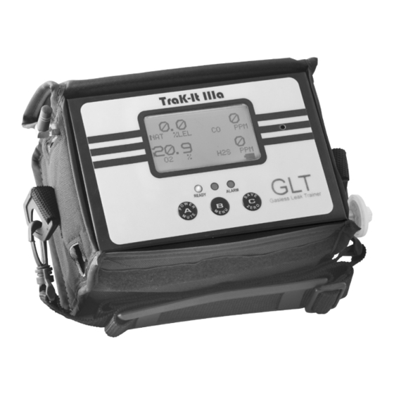
GENERAL DESCRIPTION The TRAK-IT® IIIa GLT is designed to be used in conjunction with a GLT tablet computer. The paired instrument-tablet system allows users to be trained in a hazardous gas free environment. The trainer monitors each instrument with a tablet computer running specialized software that allows real-time data to be streamed via Bluetooth from the instrument. - Page 8 GENERAL DESCRIPTION All TRAK-IT® IIIa GLT instruments incorporate a low power catalytic sensor to measure combustible gases in the LEL (lower explosive limit) range and a separate advanced thermal conductivity sensor to measure percent volume (%v/v). An automatically backlit display shows gas concentrations for all sensors installed.
-
Page 9: Specifications
SPECIFICATIONS SENSOR SPECIFICATIONS TYPE RESOLUTION RANGE ACCURACY PPM* 1 or 10ppm 0-2,000ppm ±10% 0.1%** up to 2% 0-100% LEL ±10% % NAT GAS 0.1% . 5.0-100% GAS ±5% 0.1% . 0-25% ±0.2% or 2%*** 1ppm 0-2,000ppm ±5ppm or 5%*** 1ppm 0-100ppm ±2ppm or 5%*** 1ppm... -
Page 10: Product Features
PRODUCT FEATURES BLUETOOTH GRAPHIC DISPLAY ANTENNA IR WINDOW STATUS / ALARM LEDs SPEAKER NECK STRAP OPERATIONAL BUTTONS PADDED CARRYING POUCH TRAK-IT® IIIa GLT instruments are constructed of durable stainless steel to withstand the rigors of field use. All TRAK-IT® IIIa GLT instruments require 4 Duracell MN 1400 batteries which provide 25+ hours of continuous use. - Page 11 PRODUCT FEATURES An infrared communication window is located on the right side to allow the TRAK-IT® IIIa GLT instruments to download calibration data and readings the operator has elected to save to the instrument’s on-board memory. A graphic display continuously updates the operator of all available gas concentrations and alarms simultaneously as well as indicates internal functions such as air flow and battery power.
-
Page 12: Sensor Types And Pumps
SENSOR TYPES AND PUMPS Combustible Gas Sensor All TRAK-IT® IIIa GLT instruments incorporate a poison resistant catalytic bead sensor. The function and accuracy of the sensor are monitored and controlled by specialized circuitry and a microprocessor. This sensor is capable of measuring concentrations of 50ppm up to 100%LEL. -
Page 13: Battery Installation/Replacement
BATTERY INSTALLATION/REPLACEMENT A battery strength icon is located at the lower right corner of the display which indicates the approximate battery capacity. Battery replacement is necessary when the display reads BAT LOW (4.25 Volts), an audible alarm sounds and the green ready LED flashes. When the instrument remains in BAT LOW, a count down will appear starting at 300 seconds (5 minutes) which is the maximum time remaining before shut down. -
Page 14: Operation And Use
NOTE: Instrument must be used in monitoring mode in order to read live gas. 1. Push the POWER/MUTE BUTTON (A) until the instrument beeps and the display illuminates. Each of the following will be displayed: a. Sensit Technologies Logo b. System check that includes: LED check Backlight check iii. - Page 15 OPERATION AND USE 2. If you are not using the instrument along with a GLT tablet, press and release any button on the “Wait for Trainer” screen to select monitoring mode and continue the start-up process. 3. If the display fails to illuminate or BAT LOW is shown on the display, replace the batteries.
- Page 16 OPERATION AND USE 7. Prior to use, test the integrity of the sample system. Use your finger to block the inlet of the probe assembly for 4-5 seconds. The display will read FLOW BLOCKED if all seals are intact.During pump flow block, a beep will occur every 2 seconds until the pump restarts and adequate flow is present.
- Page 17 OPERATION AND USE The standard factory preset LED indicators and alarm points are: a. Combustible gas: Methane, audio and visual alarm indicators from 10% LEL to 100% LEL. METHANE: 50% LEL Methane to 17% volume* Methane (LED indicator only above 17% volume Methane) *When equipped with percent volume sensor.
- Page 18 OPERATION AND USE 12. At any time the operator may save the readings on the display by pressing the ZERO/SAVE BUTTON (C). This will save all readings for download at a later time. Log size is factory set to store 6 logs, but can be increased up to 100 logs.
-
Page 19: Bar Hole Test
BAR HOLE TEST For percent volume equipped units To assist pinpointing the location of underground leaks, the Bar Hole Test feature may be used. This feature will draw a timed sample (20 seconds) and display sustained and peak readings. NOTE: Use an approved barhole probe with filter to prevent damage to the instrument when conducting bar hole surveys. - Page 20 BAR HOLE TEST If you have another test to take, press & hold the SAVE/ZERO BUTTON (C). This will restart the pump and clear the last readings. When the readings have returned to zero, release SAVE/ZERO BUTTON (C). The countdown timer will restart. You may encounter NSR or NSC readings during the bar hole test (see page 12 for definition).
-
Page 21: Leak Search Mode (Optional)
LEAK SEARCH (OPTIONAL) To conduct a LEAK SEARCH (LS): To enter the LEAK SEARCH mode from the work display, press and release the MENU (B) button. Press and release the SAVE/ZERO (C) button until LS is displayed on the bottom of the screen. Press and release the MENU (B) button. -
Page 22: Purge Mode
PURGE MODE NOTE: This feature is for purging lines in and out of service only (purging with line gas or air) To conduct a PURGE: To enter the PURGE mode from the work display, press and release the MENU (B) button. Press and release the SAVE/ZERO (C) button until PURGE is displayed on the bottom of the screen. -
Page 23: Calibration Check
CALIBRATION CHECK To verify the accuracy of any TRAK-IT® IIIa GLT, it must be exposed to a known concentration of test gas that will test any sensor combination included in your particular model. Any sensor that does not meet the specifications listed in this manual may require calibration or repair. -
Page 24: User Menu
USER MENU The TRAK-IT® IIIa GLT has several categories within the User Menu. The first twelve fields are standard with all instruments. The last two are only available in certain instrument models when ordered with the Extended Memory option. SHOW TIME: Displays current date and time. -
Page 25: User Menu Descriptions
USER MENU CAL LOG: Display last calibration of all sensors. SES LOG: Display saved gas readings with the corresponding date and time. BH LOG: Display barhole logs with the corresponding date and time. SMART CAL: Prepare for use with calibration station. CAL DUE: Display future calibration due dates for each gas. -
Page 26: Show Time, Set Clock
USER MENU SHOW TIME From the working display, access the menu by pressing and holding the MENU BUTTON (B) until the display reads USER MENU/SHOW TIME. Press MENU BUTTON (B) one time to display the time and date. Press any button to return to the USER MENU. SET CLOCK From the working display access the menu by pressing and holding the MENU BUTTON (B) until the top line reads USER MENU. -
Page 27: Printing To Optional Ir Printer
USER MENU PRINT For all printing operations, the printer is only to be used in non- hazardous locations. From the working display access the menu by pressing & holding the MENU BUTTON (B) until the top line of the display reads USER MENU. The bottom line will read SHOW TIME. -
Page 28: Bump Test
USER MENU BUMP TEST From the working display, press & hold the MENU BUTTON (B) until the top line reads USER MENU. Press & release the SAVE/ZERO BUTTON (C) to scroll until the bottom line reads BUMP TEST. Prepare the appropriate certified gas mixture for your instrument model (see proper gas mixtures listed in the Calibration section). -
Page 29: Cal, O2 Test
USER MENU See Calibration section on Page 38. O2 TEST From the working display press & hold the MENU BUTTON (B) until the top line reads USER MENU. Press & release the SAVE/ZERO BUTTON (C) to scroll until the bottom line reads O2 TEST. Apply recommended gas mixture void of oxygen, such as 100% Methane or 100% Nitrogen and press &... -
Page 30: Gas Type
USER MENU GAS TYPE From the working display press & hold the MENU BUTTON (B) until the top line reads USER MENU. Press & release the SAVE/ZERO BUTTON (C) until the bottom line reads GAS TYPE. Press & release the MENU BUTTON (B) To change the gas type, press &... -
Page 31: Cal Log: Show Log, Print Log
USER MENU CAL LOG To Show a Calibration Log From the working display press & hold the MENU BUTTON (B) until the top line reads USER MENU. Press & release the SAVE/ZERO BUTTON (C) to scroll until the bottom line reads CAL LOG. Press &... -
Page 32: Session Log: Show Log, Print Log
USER MENU SESSION LOG To Show a Session Log From the working display, press & hold the MENU BUTTON (B) until the top line reads USER MENU. Press & release the SAVE/ZERO BUTTON (C) to scroll until the bottom line reads SES LOG. Press & release the MENU BUTTON (B) once to enter the menu. -
Page 33: Bh Log, Smart-Cal
USER MENU SHOW BH LOG From the working display access the menu by pressing and holding the MENU BUTTON (B) until the display reads USER MENU SHOW TIME. Press the SAVE/ZERO BUTTON (C) to scroll to USER MENU SHOW BH LOG. Press MENU BUTTON (B) to select this feature. -
Page 34: Cal Due, Autolog
USER MENU CAL DUE From the working display access the menu by pressing and holding the MENU BUTTON (B) until the display reads USER MENU/SHOW TIME. Press the SAVE/ZERO BUTTON (C) to scroll to USER MENU/ CAL DUE. Press the MENU BUTTON (B) to select this feature. The heading will display CAL DUE if the sensor is past calibration or NEXT CAL indicating when the sensor is due. -
Page 35: Cf Test: Show Test, Print Test
USER MENU CF TEST Only available as an option for instruments with CO and O2 and the extended memory feature. To Conduct a CF Test NOTE: The hot air flue probe must be used with the instrument when conducting this test to prevent damage to the instrument and to receive proper calculations. - Page 36 USER MENU CF TEST If this segment continues to flash during the test period, conditions for a proper test were not possible. In this case any test results are invalid. The display and printout will show N/A for the peak CF reading.
- Page 37 USER MENU CF TEST To Show a CF Test From the working display, press & hold MENU BUTTON (B) until the top line reads USER MENU. Press & release the SAVE/ZERO BUTTON (C) to scroll until the bottom line reads CF LOG. Press &...
-
Page 38: Calibration
CALIBRATION NOTE: Calibration should be done while in Monitoring Mode. Calibration is the process of setting the readings of the instrument to equal the value of certified calibration gases. Prior to calibration allow the instrument to operate for 5 to 10 minutes in a room environment free of combustible, CO, H2S or HCN gases. -
Page 39: Calibration Auto Cal
CALIBRATION Prior to starting calibration prepare the necessary gases per the sensor configuration. From the working display access the menu by pressing and holding the MENU BUTTON (B) until the display reads USER MENU SHOW TIME. Press the SAVE/ZERO BUTTON (C) to scroll to USER MENU CAL . Press the MENU BUTTON (B) to the calibration modes. -
Page 40: Carbon Monoxide (Co) Calibration
MANUAL CALIBRATION The following instructions pertain to manual calibration of the TRAK- IT®IIIa GLT. If you are using the automatic Smart-Cal Calibration System, the procedure is different. See the Smart-Cal sections of this manual or consult the Smart-Cal instruction manual for details. CARBON MONOXIDE (CO) CALIBRATION (100PPM CO/AIR) From the working display, press &... -
Page 41: Hydrogen Sulfide (H2S) Calibration
MANUAL CALIBRATION HYDROGEN SULFIDE (H2S) CALIBRATION (H2S 25 PPM) From the working display press & hold the MENU BUTTON (B) until the top line reads USER MENU. Press & release the SAVE/ZERO BUTTON (C) until the bottom line reads CAL. Press &... -
Page 42: Hydrogen Cyanide (Hcn) Calibration
MANUAL CALIBRATION HYDROGEN CYANIDE (HCN) CALIBRATION (HCN 10 PPM) From the working display press & hold the MENU BUTTON (B) until the top line reads USER MENU. Press & release the SAVE/ZERO BUTTON (C) until the bottom line reads CAL. Press &... -
Page 43: Methane Lel Calibration (50% Lel) (2.5% Lel)
MANUAL CALIBRATION COMBUSTIBLE GAS CALIBRATION 2.5% V/V (Volume) METHANE From the working display press & hold the MENU BUTTON (B) until the top line reads USER MENU. Press & release the SAVE/ZERO BUTTON (C) until the bottom line reads CAL. Press &... -
Page 44: Methane Calibration (100%)
MANUAL CALIBRATION COMBUSTIBLE GAS CALIBRATION 100% VOLUME METHANE NOTE: After calibration of 100% Methane, it is recommended to auto- zero the unit before use. From the working display press & hold the MENU BUTTON (B) until the top line reads USER MENU. Press & release the SAVE/ZERO BUTTON (C) until the bottom line reads CAL. -
Page 45: Propane Calibration (1.1%) Or (50% Lel)
MANUAL CALIBRATION COMBUSTIBLE GAS CALIBRATION (1.1% PROPANE or 50% LEL PROPANE) From the working display press & hold the MENU BUTTON (B) until the top line reads USER MENU. Press & release the SAVE/ZERO BUTTON (C) until the bottom line reads CAL. Press & release the MENU BUTTON (B) once. -
Page 46: Oxygen Sensor Test
MANUAL CALIBRATION OXYGEN SENSOR TEST To determine if the O2 sensor is working properly, verify the sensors reaction by exposing it to a calibration gas void of oxygen, such as 100% methane or 100% nitrogen. From the working display press & hold the MENU BUTTON (B) until the top line reads USER MENU. -
Page 47: Expert Menu Feature Definitions
EXPERT MENU FEATURE DEFINITIONS CONTRAST: Set display contrast for better viewing TICK: Set normal speed of tick rate when resetting %LEL MODE: Set to LEL display. If off readings are %V/V 100% LEL: Set the value of LEL between 4-5% methane LEL RESOLUTION: Set reading increments on display NEW O2: Tracks install date N COMP: Specialized sensor compensation software... - Page 48 EXPERT MENU FEATURE DEFINITIONS POWER OFF: Automatic shut off time PURGE TIME: Run time before instrument shut down after power off BH TIME: Adjustment for the bar hole test time CF/CO TIME: Adjustment for the CO test time ERASE AUTO: Erase the AUTO LOG NG FACTOR: Factor for methane content in 100% natural gas NSR: Disable gas distinguishing software NSC: Disable combustible/inert identifier...
-
Page 49: Expert User Chart
EXPERT FEATURE CHART FEATURE SETTINGS DEFAULT SERVICE: CONTRAST 0-63 % LEL MODE ON/OFF 100%LEL N 4.0-5.0 100%LEL P 1.8-2.2 RESOLUTION 0.0-2.0 N COMP ON/OFF CAL DUE 30,45,60,90,180,360 DAYS DUE ACK ON/OFF N2 FOR O2 ON/OFF SHOW SES ON/OFF SHOW BH ON/OFF SHOW AUTO ON/OFF... - Page 50 EXPERT FEATURE CHART FEATURE SETTINGS DEFAULT POWER OFF 0-480 MIN. 60 MIN. PURGE TIME 0-120 SEC. 10 SEC. BH TIME 5-120 SEC. 20 SEC. ERASE AUTO ERASE AUTO PASSWORD REQ. NG FACTOR 50-100 ON/OFF ON/OFF NSC LEL 1.0-10.0 AUTO BUMP 0-30 MUTE LATCH ON/OFF...
-
Page 51: Lel Cross-Sensitivity
LEL CROSS SENSITIVITY When sensing other gases the methane calibrated reading may be lower than the actual LEL of the gas sensed. For example 100% LEL of propane will only display as 70% LEL. LEL Cross Sensitivity Calculation Chart The chart below shows the relative reading if exposed to 50% LEL of the most common gases this instrument may be used to detect. -
Page 52: Warranty
Units out of warranty will be repaired for a service charge. Internal repair or maintenance must be completed by a SENSIT Technologies authorized technician. Violation will void warranty. Units must be returned postpaid, insured and to the attention of the Service Dept.
Need help?
Do you have a question about the Trak-It IIIa GLT and is the answer not in the manual?
Questions and answers