SENSIT Technologies SENSIT GOLD G2 Instruction Manual
For use with combustible gases and optionally available oxygen and toxic gases
Hide thumbs
Also See for SENSIT GOLD G2:
- Quick start instructions (2 pages) ,
- Quick start instructions (2 pages) ,
- Instruction manual (56 pages)
Advertisement
Quick Links
PARTS AND ACCESSORIES
Standard Accessories (included)
Carrying Case, Alkaline Batteries, Wrist Strap, Extra Sensor Cap with O-Rings,
T10 Torx Wrench and Instruction Manual
Accessories and Replacement Parts
870-00012
Extension Adapter
873-00012
Hydrocarbon Filter (10) (Barhole Probe with
filter required)
883-00023
Hot Air Probe Assembly
883-00019
81.3cm (32") Fiberglass Bar Hole Probe w/Filter
883-00015
Confined Space Probe with Tubing
870-00004
Printer
870-00008
PC Interface with Software
914-00000-01
SMART-CAL™ Automatic Calibration System
870-00018
Sensor Cap with O-Rings
Calibration Kits
Contact factory for correct kit
WARRANTY
Your Sensit®Gold G2 is warranted to be free from defects in materials and
workmanship for a period of two years after purchase (excluding calibra-
tion and batteries). The circuit board and percent gas sensor (TC) are war-
ranted for 5 years. If within the warranty period, your instrument should
become inoperative from such defects, the unit will be repaired or replaced
at our option. This warranty covers normal use and does not cover damage
which occurs in shipment or failure which results from alteration, tampering,
accident, misuse, abuse, neglect or improper maintenance. Proof of pur-
chase may be required before warranty is rendered. Units out of warranty
will be repaired for a service charge. Internal repair or maintenance must be
completed by a SENSIT Technologies authorized technician. Violation will
void warranty. Units must be returned postpaid, insured and to the attention
of the Service Dept. for warranty or repair.
This warranty gives you specific legal rights and you may have other rights
which vary from state to state.
SENSIT Technologies
851 Transport Drive • Valparaiso, IN 46383
Phone: (219) 465-2700 • 888 4 SENSIT (473-6748)
Fax: (219) 465-2701 • www.gasleaksensors.com
INSTRUCTION MANUAL 750-00039
9-13-2010 REV. 3.0, 02.27.2012
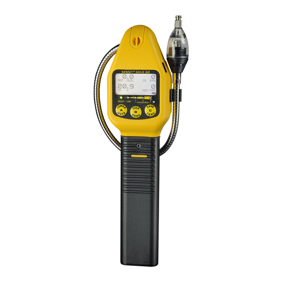
SENSIT®GOLD G2
INSTRUCTION MANUAL
For use with combustible gases
and optionally available
oxygen and toxic gases.
0891
II 2 G
Ex ib IIB T3
AEx ia IIB T3
IP54
ATEX Cert. No. TRAC11ATEX21304X
Listed UL 913
Intrinsically Safe for Use in
Class I, Groups C and D, T3
Hazardous Locations
Warning:
To prevent ignition
of flammable or
combustible
atmospheres,
disconnect power
before servicing.
SENSIT TECHNOLOGIES
851 Transport Drive
Valparaiso, IN 46383
Phone: (219) 465-2700
Fax: (219) 465-2701
US Toll Free: (888) 473-6748
www.gasleaksensors.com
Read and understand
instructions before use.
Advertisement

Related Manuals for SENSIT Technologies SENSIT GOLD G2


Summary of Contents for SENSIT Technologies SENSIT GOLD G2
- Page 1 Internal repair or maintenance must be atmospheres, completed by a SENSIT Technologies authorized technician. Violation will disconnect power void warranty. Units must be returned postpaid, insured and to the attention of the Service Dept. for warranty or repair.
- Page 2 Bar Hole Test Calibration Check (Bump Test page 21) Continuously low calibration check results or fluctuation of zero readings Menu may indicate sensor end of life or failure. Consult SENSIT Technologies Calibration with any questions. Expert User Feature Chart Back...
- Page 3 The Sensit®Gold G2 instrument is approved ATEX Zone 1 quirements change. intrinsically safe Ex ib IIB T3 IP54 and UL CLI, Div 1 Groups C & D, T3 hazardous locations. Consult Sensit Technologies for Sensit Gold G2 configurations include measuring PPM, LEL certificate details.
- Page 4 PRODUCT FEATURES PRODUCT FEATURES continued from page 4 An infrared communication window is located on the right IR COMMUNICATION LUER PROBE side to allow the Sensit®Gold G2 instrument to download cali- CONNECTOR bration data, readings the operator has elected manually to save SENSOR CAP WITH BACKLIT WATER/DIRT FILTER...
- Page 5 SENSOR TYPES AND PUMPS continued SENSOR TYPES AND PUMPS NOTE: Operating the instrument without a sensor cap or Combustible Gas Sensor with an altered sensor cap can cause damage to the in- All Sensit®Gold G2 instruments incorporate a highly sensitive strument and void the warranty.
- Page 6 Auto Log Check (alert at 50 records remaining VOL) below all readings. before memory is full and overwrites) c. Display all active sensors d. Display “SENSIT GOLD G2, Configuration Number and Software revision”. (continued on page 10) (Continued on page 9)
- Page 7 OPERATION AND USE OPERATION AND USE continued from page 9 continued from page 10 be accomplished. This adapter slides onto the battery sleeve If PPM display is selected, the measurement auto-ranges to and is held in place by the locking nut assembly. LEL at levels above 2000ppm.
- Page 8 OPERATION AND USE OPERATION AND USE continue from page 12 continue from page 11 c. Carbon Monoxide - 35ppm per utility industry standards MENU BUTTON (B) to reset the tick so that is audible. d. Hydrogen Sulfide - 10ppm and above per Federal OSHA Pressing the POWER/MUTE BUTTON (A) disables the tick guidelines e.
- Page 9 OPERATION AND USE BAR HOLE TEST continue from page 13 continued from page 14 calibrated for propane, “NSR” likely indicates gas lighter than air SAVE/ZERO BUTTON (C) display. Press to BH Test. Press & such as helium . “NSC” may indicate methane, hydrogen or release TICK/MENU BUTTON (B) to enter the BH menu.
- Page 10 MENU CALIBRATION CHECK continued from page 16 continued from page 15 CAL LOG: Display last calibration of all sensors. does not update the calibration due date. Full calibration is re- SES LOG: Display saved gas readings with the corresponding quired to update these times. date and time.
- Page 11 MENU MENU continued from page 18 continued from page 17 BUMP TEST SET CLOCK Prior to starting this test, prepare the necessary gases per From the working display access the menu by pressing and the sensor configuration. holding the TICK/MENU BUTTON (B) until the top line reads From the working display, pressing and holding the TICK/MENU USER MENU/SHOW TIME.
- Page 12 MENU MENU continued from page 19 continued from page 20 FAILED will show. Let the instrument clear and repeat the cali- MENU GAS TYPE. Press the TICK/MENU BUTTON (B) to se- bration process. If the instrument will not pass, remove the in- lect this feature.
- Page 13 MENU MENU continued from page 22 continued from page 21 USER MENU SHOW TIME. Press the SAVE/ZERO BUTTON the next record while pressing the TICK/MENU BUTTON (B) re- (C) to scroll to USER MENU SHOW CF LOG. turns you back to the previous record. Press the POWER/MUTE BUTTON (A) to return to the USER MENU.
- Page 14 MENU MENU continued from page 23 continued from page 24 AUTO LOG To Retrieve Autolog Events: AUTOLOG (Automatically included with every unit that has the Stored autolog events can be downloaded to a PC using the optional CF Test feature) serial port computer interface IR Link.
- Page 15 MENU continued from page 25 MENU continued from page 26 If the proper condition for an accurate test existed, the detected From the working display, press & release TICK/MENU BUT- CO level, calculated CF level and the peak CF level will remain TON (B) once, SELECT TEST will appear on the top line of the on the display at the end of the test.
- Page 16 NOTE: Using calibration kits other than recommended by • 10 PPM HCN indicates the calibration point of the SENSIT TECHNOLOGIES may cause inaccurate readings. hydrogen cyanide sensor. Repairs are required if any sensor fails to calibrate. Con- sult SENSIT TECHNOLOGIES for details.
- Page 17 Following each gas tested PASS or FAILED will be displayed. It of service. Please contact SENSIT TECHNOLOGIES for any is possible to manually stop the test once it is started by press- needed repairs.
- Page 18 EXPERT MENU FEATURE DEFINITIONS EXPERT USER FEATURE CHART CONTRAST: Set display contrast for better viewing TICK: Set normal speed of tick rate when resetting %LEL MODE: Set to LEL display. If off readings are %V/V 100% LEL: Set the value of LEL between 4-5% methane LEL RESOLUTION: Set reading increments on display NEW O2: Tracks install date N COMP: Specialized sensor compensation software...
Need help?
Do you have a question about the SENSIT GOLD G2 and is the answer not in the manual?
Questions and answers