
Related Manuals for SENSIT Technologies SPOD


Summary of Contents for SENSIT Technologies SPOD
- Page 1 SENSIT SPOD Sensor Operation Manual and Configuration Guide Version 1.0, August 12, 2019 jmelby@gasleaksensors.com For Questions Contact:...
-
Page 2: Overview Parameter
SPOD Sensor Overview General Overview Parameter Weight Base unit: 6.75 lbs Dimensions Fully assembled with anemometer and antenna • D x W x H (6” x 8” x 16”) Mounting Attached mounting flanges Voltage Requirements 18V – 24V DC Charging (wired adapter or solar panel) - Page 3 Notes: 1. Battery backup time depends on run mode and frequency of transmission. 2. Limited by lithium ion charging temperature. Lower temperature operation will require external or internal heating to maintain sufficient battery temperature for charge acceptance. Contact the manufacturer for more information.
- Page 4 3. Factory calibration conducted with 1ppm isobutylene and ultra zero air 4. PID Sensors are sensitive to high amounts of humidity and may rail at the upper output if humidity is excessive. The SPOD contains an internal sensor heater to minimize humidity interference.
-
Page 5: Cellular Specifications
Cellular Specifications Overview Parameter Network Technology 4G/2G Carrier AT&T and T-mobile Transport Layer TCP Internet Layer IP Application Layer HTTP and MQTT Data Transfer Method HTTP POST or MQTT Topics HTTP Content Type application/x-www-form-urlencoded HTTP Body Field Identifiers &ID, &MODULE, &STAT, &DATA MQTT Content Type JSON MQTT Tags “deviceId”, “time”, “iodb”... - Page 6 Sensor Exterior Features (Front Exterior)
- Page 7 Sensor Interior Features (Front Interior)
- Page 8 Sensor Interior LED Indication Cellular Status: Red LED if failure, Green LED if successful Charging Status: Green LED if Charging Calibration Mode: Solid/Flashing Blue LED in Calibration Sensor Status: Red LED if initialization failure (PID or Weather Station) SD Card Status: Red LED if failure, Green LED if successful...
- Page 9 4) After verifying functionality remove the USB cable. If planning to run in USB mode, install a power adapter or a solar panel for long term deployment applications. Otherwise, power cycle the SPOD, then install a power adapter or a solar panel for long term deployment applications.
- Page 10 Quick Start Deployment Guide (No Computer) Unpack the sensor unit and check for any physical damage or obstructions at the sensor openings. Open enclosure cover and check for any loose or damaged components. Make sure all wires are securely fastened as shown in the internal sensor view on page 7 and refer to the LEDs indicated on page 8.
- Page 11 USB Output Headings and Description USB Heading Description Units/Format DATE Local Date and Time MM/DD/YY HH:MM:SS (24H) PID1 Field 1, Sensor 1 VOC Field 2, Sensor 1 Raw Field 1, Sensor 2 VOC PID2 Field 2, Sensor 2 Raw T Temperature °C RH Relative Humidity P Pressure...
- Page 12 Ultrasonic Anemometer Mounting Instructions...
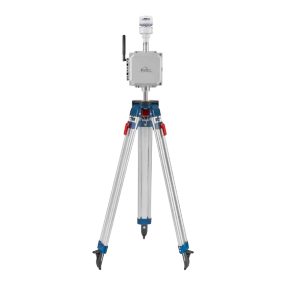
- Page 13 Tripod Setup and Installation (Optional) 1) Remove protective rubber feet if installing outdoors 2) Install pole on tripod. Pole mounting attachment may differ from image below. 3) Set leg height of tripod and spread legs with a minimum of 30° from perpendicular 4) For added stability in high wind or long-term deployments place sandbags against all legs...
- Page 14 5) Use the shorter ¼” long screw to attach pole mount to back of SPOD 6) Use the longer 1 ¼” long screw + nut to tighten on pole 7) Tighten sufficiently to prevent rotation 8) Place SPOD as far up as possible on pole to avoid blocking anemometer Note: The images below are used for reference.
- Page 15 Solar Panel Setup and Installation (Optional) 1) Lift up on side with 2 knobs to unfold panel 2) Fold down angular supports on both sides and remove 2 knobs on bottom 3) Reattach knobs vertical angular supports on both sides (flat washer, lock washer, wing nut)
- Page 16 5) Avoid shadowing on panel as much as possible as this will drastically reduce panel output power and efficiency 6) Route cable to SPOD unit 7) Plug cable into SPOD “Power/USB” connection 8) Power on SPOD unit Note: Alternative solar mounts and solar panel extension cables can be purchased from Sensit.
- Page 17 - Computer with a serial port terminal software program (e.g. CoolTerm) Sensor Quickstart Instructions 1) Connect the USB cable to the SPOD and computer and establish the communication link in the terminal software. 2) Turn on power switch and observe initialization process. After initializing the...
- Page 18 Menu Item Description Location CELLULAR Common settings Root Menu DEFAULT System Default Settings Root Menu DISPLAY Prints Current Settings Root Menu GPS Settings Root Menu HEAT Sensor Heater Settings Root Menu OFFSET Sensor Offset Setting Root Menu POWER Power Settings Root Menu SAMPLE Trigger Sample Settings...
- Page 19 Server Address: sensit-test-hub.azure-devices.net Access Point Name: zipitwireless.com.attz GPS Mode: Interval Sensor Heater: Enabled Temp Set: 15 Dew Point Control: Disabled Humidity Threshold: 80 Temp Set: 15 PID1 Offset Value (ppb): 0.00 Sample Trigger Value (ppb): 500 Trigger Average Time (sec): 10 Sample Collection Time (sec): 30 GPS: “ENABLE”...
- Page 20 POWER: Select “SOLAR” and “AC” power. If “SOLAR” is selected the unit will try to charge the batteries whenever power is present. If “AC” is selected the system will maintain the battery voltage in the middle of its range to extend battery life. It is very important that “SOLAR”...
- Page 21 HOST: Set the server address to send the data to. The target server must be configured to accept the data. NETWORK: Define network behavior of the cellular module. AUTO mode is enabled by default and under most circumstances will work well. If required it is possible to force the modem to only look for “CAT M1”, “NB IoT”, or “2G”...
- Page 22 X Value Meaning CSQ Value < -113 Absolutely no Signal -111 Very Weak Signal 2-10 -109 to -93 Weak Signal 10-20 -81 to -73 Moderate Signal 21-30 -71 to -53 Strong Signal > -51 Very Strong Signal Unknown/Not Detected Y Value Meaning Reliable Data Link Occasional Dropped Posts...
- Page 23 EXIT Exit Output Menu Output Menu MODE: Sets the communication mode of the SPOD. The following options are possible: “Cellular”: Sends data with cellular modem at ODR and USB/Power port at 1Hz “USB”: Sends data with USB/Power Port at 1Hz...
- Page 24 ODR: Sets the output data rate of the cellular modem or XBEE wireless device. The USB port will always show data output at 1Hz POLL: Disable streaming over USB/Port and XBEE. SPOD will return data when receiving any character from control device.
- Page 25 Sensor Maintenance and Calibration Periodic Maintenance: The SPOD is a low maintenance device and is designed to operate remotely with no user intervention. Occasional inspections for damage and cleanliness are recommended to maintain optimum performance. Sensor Calibration: Depending on application requirements and environmental conditions, periodic calibrations may be required to maintain target accuracy.
- Page 26 Hardware and Software Installation Guide 1) Download drivers for FTDI Serial Adapter and install drivers http://www.ftdichip.com/Drivers/VCP.htm 2) Open serial terminal program of your choice. CoolTerm is recommended and instructions for using CoolTerm are found below. CoolTerm is available for Windows, Mac, and Linux. CoolTerm can be downloaded for free from here: http://freeware.the-meiers.org/ 1) Extract ‘Software_CoolTerm’...
- Page 27 3) Click ‘Options’ as shown below a. ‘Serial Port’ options should open by default. If not, select Serial Port options from the list of available options as shown below. All default options should be correct but please verify. Click on ‘Port’ dropdown list and make note of any available ports.
- Page 28 b. Select ‘Terminal’ options from list of available options and select ‘Line Mode’ as shown below. Line mode adds a text entry bar at the bottom of the screen that is useful for sending commands to the connectedsensor.
- Page 29 c. Select ‘Receive’ options from list of available options and check “Ignore Receive Signal Errors”. Selecting this option reduces the possibility of the serial connection closing upon a received serial error such as connecting or disconnecting the cable or power cycling the unit.
- Page 30 4) To avoid having to configure the terminal every time you open it, you have 2 options to save the configuration as shown in Figure 4. a. Click “Save As” and save the connection settings as a file that you can share or store on the computer b.
- Page 31 5) Coolterm can be configured to record all data received over serial. This will be useful for evaluation purposes. ⌘ a. To start a capture go to ‘Connection’ dropdown menu Capture to Textfile Start or hit Ctrl-R ( -R).
- Page 32 Warranty Your SENSIT SPOD is warranted to be free from defects in materials and workmanship for a period of one year after purchase. If within the warranty period the instrument should become inoperative from such defects the instrument will be repaired or replaced at our option.
Need help?
Do you have a question about the SPOD and is the answer not in the manual?
Questions and answers