Table of Contents
Advertisement
Quick Links
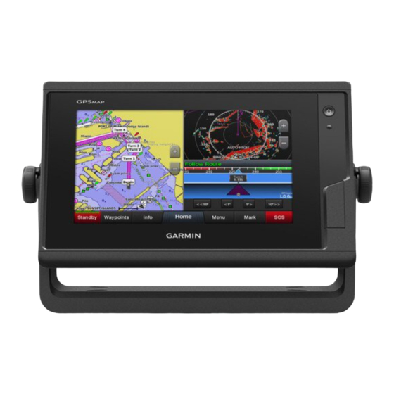
GPSMAP
®
INSTALLATION
INSTRUCTIONS
Important Safety Information
Failure to follow these warnings, cautions, and notices could
result in personal injury, damage to the vessel or device, or poor
product performance.
See the Important Safety and Product Information guide in the
product box for product warnings and other important
information.
When connecting the power cable, do not remove the in-line
fuse holder. To prevent the possibility of injury or product
damage caused by fire or overheating, the appropriate fuse
must be in place as indicated in the product specifications. In
addition, connecting the power cable without the appropriate
fuse in place voids the product warranty.
Always wear safety goggles, ear protection, and a dust mask
when drilling, cutting, or sanding.
To avoid possible personal injury or damage to the device and
vessel, disconnect the vessel's power supply before beginning
to install the device.
To avoid possible personal injury or damage to the device or
vessel, before applying power to the device, make sure that it
has been properly grounded, following the instructions in the
guide.
For the best possible performance, the device must be installed
according to these instructions.
When drilling or cutting, always check what is on the opposite
side of the surface to avoid damaging the vessel.
Read all installation instructions before proceeding with the
installation. If you experience difficulty during the installation,
contact Garmin
Product Support.
®
Contacting Garmin Support
• Go to
support.garmin.com
product manuals, frequently asked questions, videos, and
customer support.
• In the USA, call 913-397-8200 or 1-800-800-1020.
• In the UK, call 0808 238 0000.
• In Europe, call +44 (0) 870 850 1241.
November 2020
7X2/9X2 PLUS
WARNING
CAUTION
NOTICE
for help and information, such as
Software Update
You may need to update the chartplotter software after
installation. For the instructions on how to update the software,
see the owner's manual at
-9x2Plus.
Tools Needed
• Drill
• Drill bits appropriate for the device and mounting style
Mounting Style
Bail with included M4 wood screws
Flush
Flush with included M3.5 wood screws (702 series) 2 mm (
Flush with included M4 wood screws (902 series)
Flush with included machine screws and nut plates 6 mm (
Flush with included M3.5 machine screws and
tapped holes (702 series)
Flush with included M4 machine screws and tapped
holes (902 series)
• #2 Phillips screwdriver
• Jigsaw or rotary tool
• File and sandpaper
• Marine sealant (recommended)
Mounting Considerations
This device should be mounted in a location that is not exposed
to extreme temperatures or conditions. The temperature range
for this device is listed in the product specifications. Extended
exposure to temperatures exceeding the specified temperature
range, in storage or operating conditions, may cause device
failure. Extreme-temperature-induced damage and related
consequences are not covered by the warranty.
When selecting a mounting location, you should observe these
considerations.
• The location should provide optimal viewing as you operate
your boat.
• The location should allow for easy access to all device
interfaces, such as the keypad, touchscreen, and card
reader, if applicable.
• The location must be strong enough to support the weight of
the device and protect it from excessive vibration or shock.
• To avoid interference with a magnetic compass, the device
should not be installed closer to a compass than the
compass-safe distance value listed in the product
specifications.
• The location must allow room for the routing and connection
of all cables.
• The location must not be a flat, horizontal surface. The
location should be in a vertical angle.
The location and viewing angle should be tested before you
install the device. High viewing angles from above and below
the display may result in a poor image.
Bail Mounting the Device
If you are mounting the bracket on fiberglass with screws, it is
recommended to use a countersink bit to drill a clearance
counterbore through only the top gel-coat layer. This will help to
GUID-58383C42-BCE0-4965-BFF1-A648A7E884FC v2
garmin.com/manuals/GPSMAP7x2
Drill Bit Sizes
3.2 mm (
13 mm (
3.2 mm (
4 mm (
M3.5 tap
M4 tap
NOTICE
NOTICE
1
/
in.)
8
1
/
in.)
2
5
/
in.)
64
1
/
in.)
8
1
/
in.)
4
3
/
in.)
16
Advertisement
Table of Contents

Related Manuals for Garmin GPSMAP 7X2 PLUS


Summary of Contents for Garmin GPSMAP 7X2 PLUS
- Page 1 Product Support. ® • The location must not be a flat, horizontal surface. The location should be in a vertical angle. Contacting Garmin Support • Go to support.garmin.com for help and information, such as The location and viewing angle should be tested before you product manuals, frequently asked questions, videos, and install the device.
-
Page 2: Flush Mounting The Device
avoid cracking in the gel-coat layer when the screws are If the mounting holes on the device do not line up, mark the tightened. new hole locations. Based on your mounting surface and model, drill or punch You can use the included bracket to bail mount the device on a and tap the larger holes: flat surface. -
Page 3: Cable And Connection Considerations
• The wiring harness connects the device to power, NMEA • A Garmin Marine Network cable must be used for all Garmin 0183 devices, and a lamp or a horn for visible or audible Marine Network connections. -
Page 4: Nmea 0183 Connection Considerations
NMEA 2000 network. If you do not have an existing NMEA 2000 and receiving data. You can also use this diagram for one-way network you can create a basic one using cables from Garmin. communication. To receive information from a NMEA 0183... -
Page 5: Lamp And Horn Connections
• The CVBS IN port uses a BNC connector. You can use a BNC to RCA adapter to connect a composite-video source with RCA connectors to the CVBS IN port. • Video is shared across the Garmin Marine Network, but it is Item Description not shared across the NMEA 2000 network. -
Page 6: Nmea 0183 Information
Max. power usage at 10 Vdc 27 W Description Typical current draw at 12 Vdc 1.3 A 127503 AC input status (obsolete) Max. current draw at 12 Vdc 2.3 A 127504 AC output status (obsolete) Memory card 2 microSD card slots; 32 GB max. card 127506 DC detailed status size... - Page 7 , and GPSMAP ® are trademarks of Garmin Ltd. or its subsidiaries, registered in the USA and other countries. These trademarks may not be used without the express permission of Garmin. FLIR ® is a registered trademark of FLIR Systems, Inc. NMEA ®...
- Page 8 © 2019 Garmin Ltd. or its subsidiaries support.garmin.com...
Need help?
Do you have a question about the GPSMAP 7X2 PLUS and is the answer not in the manual?
Questions and answers