Table of Contents
Advertisement
Quick Links
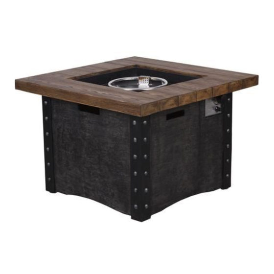
Monroe Fire Table
ITM./ART.#: 2595163
MODEL#: F180060
ANS Z21.97 CSA 2.41-2017
Outdoor Decorative Gas Appliances
Maximum inlet supply pressure: 13 in wc (3.24KPa)
Minimum inlet supply pressure: 8 in wc (1.99 KPa)
INSTALLER: Leave this manual with the appliance.
CONSUMER: Retain this manual for future reference.
DANGER
FIRE OR EXPLOSION HAZARD
If you smell gas:
Shut off gas to the appliance.
Extinguish any open flame.
If odor continues, leave the area immediately.
After leaving the area, call your gas supplier or fire
department.
Failure to follow these instructions could result in
fire or explosion, which could cause property
damage, personal injury, or death.
DANGER
WARNING:
If the information in this manual is not followed exactly, a fire or explosion may result causing
property damage, personal injury, or loss of life.
CARBON MONOXIDE HAZARD
This appliance can produce carbon monoxide which has no odor.
Using it in an enclosed space can kill you.
Never use this appliance in an enclosed space such as a camper,
tent, car or home.
WARNING: For Outdoor Use Only.
Installation and service must be
performed by a qualified installer,
service agency, or the gas supplier.
WARNING
Do not store or use gasoline, or other
flammable vapors and liquids,in the
vicinity of this or any other
appliance.
An LP-cylinder not connected for use
shall not be stored in the vicinity of
this or any other appliance.
01
Advertisement
Table of Contents

Subscribe to Our Youtube Channel
Related Manuals for Backyard Creations Monroe F180060


Summary of Contents for Backyard Creations Monroe F180060
- Page 1 Monroe Fire Table ITM./ART.#: 2595163 MODEL#: F180060 ANS Z21.97 CSA 2.41-2017 Outdoor Decorative Gas Appliances Maximum inlet supply pressure: 13 in wc (3.24KPa) Minimum inlet supply pressure: 8 in wc (1.99 KPa) INSTALLER: Leave this manual with the appliance. WARNING: For Outdoor Use Only. CONSUMER: Retain this manual for future reference.
-
Page 2: Important Safety Information
IMPORTANT SAFETY INFORMATION The installation must conform with local codes or, in the absence of local codes, with the National Fuel Gas Code, ANSI Z223.1 NFPA 54; National Fuel Gas Code; Natural Gas and Propane Installation Code, CSA B149.1; ● or Propane Storage and Handling Code, CSA B149.2, as applicable. -
Page 3: Specifications
IMPORTANT SAFETY INFORMATION ABOUT PROPANE (LP) GAS The LP-gas supply cylinder to be used must be constructed and marked in accordance with the U.S. Deparment of Transportation (D.O.T.) Specifications for LP-Gas Cylinders, or the Standard for Cylinders, Spheres and Tubes for Transportation of Dangerous Goods and Commission, CAN/CSA-B339, as applicable. The LP-gas supply cylinder to be used must have a listed overfilling prevention device (See Figure 1). -
Page 4: Package Contents
PACKAGE CONTENTS PART DESCRIPTION QUANTITY Fire Table 1 pc 1 pc Door 1 pc Weather cover 1 pc Natural gas orifice 1 pc Lava rock (13.2 Ibs) 2 boxes ASSEMBLY INSTRUCTIONS Carefully unpack all parts from the box, compare parts with package content listed above, make sure all parts are present before beginning assembly of product. - Page 5 black handle Figure 4 Figure 3 4. Attach the door (B) with fire table (A) tenderly (See Figure 5). Place the Lid (C) onto the fire bowl when not in use to protect it from the elements or when fire pit is cool COMPLETELY after the use (See Figure 6). Figure 5 Figure 6 5.
-
Page 6: Natural Gas Conversion
STOP STOP NATURAL GAS CONVERSION Natural gas conversion must be performed only by natural gas provider or service company. 1. Disconnect the propane hose from the gas valve (See Figure 8). gas valve propane hose Figure 8 2. Unscrew and disconnect the propane orifice from the bellows (See Figure 9). Propane orifice (dia2.21mm size) is painted with red mark. - Page 7 4. Connect the natural gas hose with the gas valve by screwing clockwise tightly (See Figure 11). Plug the natural gas fixture into the natrual gas supply piping system (See Figure 12). gas valve natural gas supply natural gas fixture piping system natural gas hose Figure 11...
- Page 8 BATTERY Make sure the control knob is in the “OFF” position. Unscrew the push button cap on the ignitor module located on the control panel to access the battery compartment. The ignitor module requires one AAA size battery. BATTERY IS NOT INCLUDED. (See Figure 14). WARNING: 1.
-
Page 9: Lighting Instructions
inlet tube-bellows connection (Figure 18) gas valve-hose connection (Figure 17) To perform a leak test: 1. Make 2~3 oz. of leak solution by mixing one part liquid dishwashing detergent and three parts water. Noted: make sure control knob is “OFF”. 2. -
Page 10: Care And Maintenance
Observe Flame Height When Lit: The burner will display blue and yellow flames. These flames should be a blue / yellow color between 1~2 in. height (See Figure 20). These flames should not be yellow or produce thick smoke. This would indicate an obstruction of airflow through the burners. The flames should be blue with straight yellow tops. -
Page 11: Warranty
WARRANTY Firepits Burner, steel fire pit bowl, all mechanical parts and fittings to control panel and burner assembly, and all fire pit tops that are not cast aluminum are warranted for a period of one (1) year from original date of purchase, against defects in material and or workmanship.
Need help?
Do you have a question about the Monroe F180060 and is the answer not in the manual?
Questions and answers
I'm looking to purchase the Weather cover, PN: 2595163-D and would like to know where to purchase and the cost.