Table of Contents
Advertisement
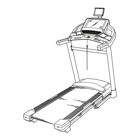
Model No. PETL99819.0
Serial No.
Write the serial number in the space
above for reference.
Serial Number
Decal
CUSTOMER SERVICE
UNITED KINGDOM
Call: 0330 123 1045
From Ireland: 053 92 36102
Website: iconsupport.eu
E-mail: csuk@iconeurope.com
Write:
ICON Health & Fitness, Ltd.
Unit 4, Westgate Court
Silkwood Park
OSSETT
WF5 9TT
UNITED KINGDOM
AUSTRALIA
Call: 1800 993 770
E-mail: australiacc@iconfitness.com
Write:
ICON Health & Fitness
PO Box 635
WINSTON HILLS NSW 2153
AUSTRALIA
CAUTION
Read all precautions and
instructions in this manual before
using this equipment. Save this
manual for future reference.
USER'S MANUAL
iconeurope.com
Advertisement
Table of Contents

Related Manuals for Pro-Form PERFORMANCE 800i


Summary of Contents for Pro-Form PERFORMANCE 800i
- Page 1 Model No. PETL99819.0 Serial No. USER’S MANUAL Write the serial number in the space above for reference. Serial Number Decal CUSTOMER SERVICE UNITED KINGDOM Call: 0330 123 1045 From Ireland: 053 92 36102 Website: iconsupport.eu E-mail: csuk@iconeurope.com Write: ICON Health & Fitness, Ltd. Unit 4, Westgate Court Silkwood Park OSSETT...
-
Page 2: Table Of Contents
TABLE OF CONTENTS WARNING DECAL PLACEMENT ............. . . 2 IMPORTANT PRECAUTIONS . -
Page 3: Important Precautions
IMPORTANT PRECAUTIONS WARNING: To reduce the risk of burns, fire, electric shock, or injury to persons, read all important precautions and instructions in this manual and all warnings on your treadmill before using your treadmill. ICON assumes no responsibility for personal injury or property damage sus- tained by or through the use of this product. - Page 4 21. The treadmill is capable of high speeds. frame securely in the storage position. Do Adjust the speed in small increments to not operate the treadmill while it is folded. avoid sudden jumps in speed. 26. Do not change the incline of the treadmill by 22.
-
Page 5: Before You Begin
Thank you for selecting the new PROFORM ® reading this manual, please see the front cover of this PERFORMANCE 800I treadmill. The PERFORMANCE manual. To help us assist you, note the product model 800I treadmill provides an impressive selection of fea- number and serial number before contacting us. -
Page 6: Part Identification Chart
PART IDENTIFICATION CHART Use the drawings below to identify small parts used for assembly. The number in parentheses below each draw- ing is the key number of the part, from the PART LIST near the end of this manual. The number following the key number is the quantity used for assembly. -
Page 7: Assembly
ASSEMBLY • Assembly requires two persons. • Left parts are marked “L” or “Left” and right parts are marked “R” or “Right.” • Place all parts in a cleared area and remove the packing materials. Do not dispose of the packing •... - Page 8 2. Make sure that the power cord is unplugged. Remove the tie securing the Upright Wire (80) to the front of the Base (88). Next, identify the Right Upright (79). Have a second person hold the Right Upright near the Base (88).
- Page 9 4. Set the Right Upright (79) on the Base (88) as shown. Make sure not to pinch the Upright Wire (80). Then, slide the Right Upright so that the 3/8" x 2 3/8" Screw (2) in the Base is inserted into the slot in the Right Upright. Do not tighten the Screw yet.
- Page 10 6. Remove and save the four indicated 5/16" x 3/4" Screws (13). Identify the Left and Right Base Covers (94, 95). Slide the Left Base Cover onto the Left Upright (78), and slide the Right Base Cover onto the Right Upright (79). Do not press the Base Covers into place yet.
- Page 11 9. Set the Console Base (97) face down on a soft surface to avoid scratching the Console Base. Remove and discard the two indicated screws (F). Then, remove the Pulse Crossbar (75). Next, identify the Left and Right Trays (85, 86). Attach the Trays to the Console Base (97) with eight #8 x 1/2"...
- Page 12 11. With the help of a second person, hold the con- sole assembly (G) near the Handrails (72). Connect the ground wires (H) from the console assembly (G) to the Console Ground Wires (76) on the Pulse Crossbar (75). Next, insert the Upright Wire (80) through the two indicated looped ties (I).
- Page 13 13. Attach the Pulse Crossbar (75) to the console assembly (G) with four #8 x 3/4" Screws (11); start all four Screws, and then tighten them. Do not overtighten the Screws. Firmly tighten the four 5/16" x 3/4" Screws (13). 14.
- Page 14 15. Raise the Frame (54) to the upright position. Have a second person hold the Frame until step 17 is completed. Remove the two 5/16" x 3/4" Screws (13) from the Latch Crossbar (51). Next, orient the Latch Crossbar (51) as shown. Make sure that the “This side toward belt”...
- Page 15 17. Remove the 5/16" Nut (14) and the 5/16" x 2 1/4" Bolt (26) from the bracket on the Latch Crossbar (51). Align the upper end of the Storage Latch (52) with the bracket on the Latch Crossbar (51), and insert the 5/16"...
- Page 16 19. Firmly tighten the three Screws (2, 3, 4) on each side of the treadmill, and press the Base Covers 2, 3, 4 (94, 95) into place. 2, 3, 4 20. Make sure that all parts are properly tightened before you use the treadmill. If there are sheets of plastic on the treadmill decals, remove the plastic.
-
Page 17: How To Use The Treadmill
HOW TO USE THE TREADMILL HOW TO PLUG IN THE POWER CORD Follow the steps below to plug in the power cord. This product must be earthed. If it should malfunc- 1. Plug the indicated end of the power cord into the tion or break down, earthing provides a path of least socket on the treadmill. - Page 18 CONSOLE DIAGRAM FEATURES OF THE CONSOLE In addition, the console features a selection of workouts. Each workout automatically controls the The advanced treadmill console offers a selection of speed and incline of the treadmill as it guides you features designed to make your workouts more effec- through an effective exercise session.
- Page 19 HOW TO TURN ON THE POWER HOW TO USE THE TOUCH SCREEN IMPORTANT: If the treadmill has been exposed to The console features a tablet with a full-color touch cold temperatures, allow it to warm to room tem- screen. The following information will help you become perature before you turn on the power.
- Page 20 HOW TO SET UP THE CONSOLE 6. Calibrate the incline system. Before using the treadmill for the first time, set up the First, touch your name on the screen. Next, select console. the settings main menu. Then, select the mainte- nance section, touch the Calibrate Incline button, 1.
- Page 21 HOW TO USE THE MANUAL MODE 4. Change the incline of the treadmill as desired. 1. Insert the key into the console. To change the incline of the treadmill, press the incline increase and decrease buttons or one of the See HOW TO TURN ON THE POWER on numbered incline buttons.
- Page 22 • Your pace To measure your heart rate, stand on the foot rails and hold the contacts with your palms for • The speed of the walking belt approximately ten seconds; avoid moving your hands. When your pulse is detected, your heart •...
- Page 23 HOW TO USE A MAP WORKOUT 5. Monitor your progress with the display modes. Note: To use a map workout, the console must be con- See step 5 on page 21. nected to a wireless network (see HOW TO USE THE WIRELESS NETWORK MODE on page 27).
- Page 24 If you make a mistake, you can use the Undo but- HOW TO USE A DISTANCE OR TIME WORKOUT ton on the left side of the screen. Note: To use a distance or time workout, the console The screen will display the elevation and distance must be connected to a wireless network (see HOW statistics for your workout.
- Page 25 5. Select a distance or time workout that you have HOW TO USE THE WORKOUT SETTINGS SECTION previously added to your schedule on iFit.com. 1. Select the settings main menu. Touch the calendar icon to download a distance or time workout from your schedule. Insert the key into the console (see HOW TO TURN ON THE POWER on page 19).
- Page 26 HOW TO USE THE EQUIPMENT SETTINGS HOW TO USE THE MAINTENANCE SECTION SECTION 1. Select the settings main menu. 1. Select the settings main menu. See step 1 on page 25. See step 1 on page 25. 2. Select the maintenance section. 2.
- Page 27 4. Calibrate the incline system of the treadmill. HOW TO USE THE WIRELESS NETWORK MODE Touch the Calibrate Incline button. Then, touch the The console features a wireless network mode that Begin button to calibrate the incline system. The allows you to set up a wireless network connection. treadmill will automatically rise to the maximum incline level, lower to the minimum incline level, 1.
- Page 28 When the console is connected to your wireless THE OPTIONAL CHEST HEART RATE MONITOR network, a checkmark will appear next to the wire- less network name. Then, touch the back button on Whether your the screen to return to the wireless network mode. goal is to burn fat or to To disconnect from a wireless network, touch and...
-
Page 29: How To Fold And Move The Treadmill
HOW TO FOLD AND MOVE THE TREADMILL HOW TO FOLD THE TREADMILL HOW TO MOVE THE TREADMILL To avoid damaging the treadmill, adjust the incline Before moving the treadmill, fold it as described at the to zero before you fold the treadmill. Then, remove left. -
Page 30: Maintenance And Troubleshooting
MAINTENANCE AND TROUBLESHOOTING MAINTENANCE SYMPTOM: The power turns off during use Regular maintenance is important for optimal per- a. Check the power switch (see drawing c at the left). formance and to reduce wear. Inspect and properly If the switch has tripped, wait for five minutes and tighten all parts each time the treadmill is used. - Page 31 Next, locate the Reed Switch (100) and the Magnet SYMPTOM: The incline of the treadmill does not (102) on the left side of the Pulley (46). Turn the change correctly Pulley until the Magnet is aligned with the Reed Switch. Make sure that the gap between the a.
- Page 32 d. If the walking belt still slows when walked on, see SYMPTOM: The walking belt slips when walked on the front cover of this manual. a. First, remove the key and UNPLUG THE POWER SYMPTOM: The treadmill will not connect to the CORD.
-
Page 33: Exercise Guidelines
EXERCISE GUIDELINES Burning Fat—To burn fat effectively, you must exer- WARNING: cise at a low intensity level for a sustained period of Before beginning this time. During the first few minutes of exercise, your or any exercise program, consult your physi- body uses carbohydrate calories for energy. -
Page 34: Part List
PART LIST Model No. PETL99819.0 R0719A Key No. Qty. Description Key No. Qty. Description #8 x 1/2" Ground Screw Latch Crossbar 3/8" x 2 3/8" Screw Storage Latch 3/8" x 1 1/4" Screw Motor Belt 3/8" x 1 1/2" Screw Frame 5/16"... - Page 35 Key No. Qty. Description Key No. Qty. Description Clamp #8 x 1/2" Machine Screw Magnet Filter 5/16" Washer Motor Isolator Motor Bushing Ferrite Clamp #8 Nut Receptacle Controller Clamp – User’s Manual Note: Specifications are subject to change without notice. For information about ordering replacement parts, see the back cover of this manual.
-
Page 36: Exploded Drawing
EXPLODED DRAWING A Model No. PETL99819.0 R0719A... - Page 37 EXPLODED DRAWING B Model No. PETL99819.0 R0719A...
- Page 38 EXPLODED DRAWING C Model No. PETL99819.0 R0719A 90 36...
- Page 39 EXPLODED DRAWING D Model No. PETL99819.0 R0719A...
-
Page 40: Ordering Replacement Parts
ORDERING REPLACEMENT PARTS To order replacement parts, please see the front cover of this manual. To help us assist you, be prepared to provide the following information when contacting us: • the model number and serial number of the product (see the front cover of this manual) •...
Need help?
Do you have a question about the PERFORMANCE 800i and is the answer not in the manual?
Questions and answers