Advertisement
Advertisement

Related Manuals for ANDELI MCT Series


Summary of Contents for ANDELI MCT Series
- Page 1 OWNER'S MANUAL MCT-520DPL PRO MULTIFUCTION WELDING&CUTTING MACHINE...
-
Page 2: Table Of Contents
CONTENTS 1. BRIEF INSTRUCTION ..................2 2. SAFETY WARNING ..................... 3 3. TECHNICAL PARAMETERS TABLE .............. 4 Structure of welder .................5 5. INSTALLATION INSTRUCTION ..............7 6. PRECAUTIONS ....................13 7. TROUBLESHOOTING AND FAULT FINDING ......... 14 8. EXPLOSIVE VIEW ....................19... -
Page 3: Brief Instruction
1. BRIEF INSTRUCTION MCT series welding machine is the latest multi-purpose machine developed by our company. It is suitable for all kinds of metal cutting machines, argon arc welding and manual arc welding. Its biggest feature is that it can cut stainless steel, alloy steel, carbon steel, and other non-ferrous metals with cutting function, or it can weld stainless steel and carbon steel products with DC function. -
Page 4: Safety Warning
2. SAFETY WARNING Welding and cutting is dangerous to the operator, people in or near the working area, and the surrounding, if the machine is not correctly operated. Therefore, the performance of welding/cutting must only be under the strict and comprehensive observance of all relevant safety regulations. -
Page 5: Technical Parameters Table
3. TECHNICAL PARAMETERS TABLE Model M CT-520DPL PRO Parameters Mode Input voltage( V) AC220±15% Frequency (Hz) 50/60 Rate input current( A) Current Range( A) 20-50 10-200 10-200 50-200 No-load voltage( V) Rate output voltage ( V) Remote control Ignition way TOUCH TOUCH Efficiency(... -
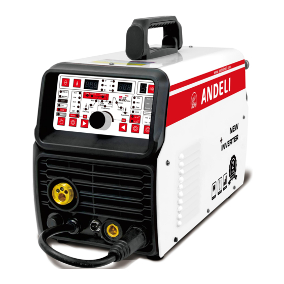
Page 6: Structure Of Welder
4. Structure of welder Figure 1 1. Control panel panel schematic Refer details 2. MIG Torch ‘Euro Style’ Connection Socket 3. TIG/CUT Torch Connection Socket 4. Polarconversion line 5. Aero socket -For spool gun function Figure 2 6. Positive (+) Welding Output Terminal 7. - Page 7 panel description: M CT-520DPL PRO Wire Check Button Welding model selection: MIG 2T/MIG 4T, Plasma CUT, HF TIG, SPOT, MMA MIG Synergic/MIG Manual/TIG PULSE Selection: Press to select MIG Synergic mode (wire diameter) or MIG Manual mode or DC Pulse TIG TIG Parameter Selection Button: Press to select different TIG parameters (move right) Parameter Adjust Knob: Adjust to increase or decrease various parameters TIG Parameter Selection Button: Press to select different TIG parameters (move left)
-
Page 8: Installation Instruction
5. INSTALLATION INSTRUCTION The machine is equipped with power voltage compensation device. When the power voltage fluctuates between±15% of rated voltage, it still can work normally. When the machine is used with long cables, in order to prevent voltage form going down, bigger section cable is suggested. - Page 9 Welding Set Up & Operation NOTE: Please connect the power line of the welder to the input voltage consistent with the parameters on the machine nameplate. .5.1Welding wire reel installation Loose wire spool retaining knob,install the wire reel on the holder of wire feeding machine, the hole of wire reel should align with fixed pin on the holder.
- Page 10 5.5.2MIG Welding Installation Connect the MIG Torch Euro Connector to the torch socket on the front of the welder . Secure by firmly gas cylinder hand tightening the threaded collar on the MIG 220V Torch Euro Connector clockwise. Check that the correct gas shielded wire, matching drive roller and welding tip...
- Page 11 5.5.3 TIG Welding Installation Connect Lift TIG torch Quick Connector to gas cylinder 220V the negative (-) output welding terminal. Connect Earth Lead Quick Connectorto the positive (+) welding output terminal. Connect the air hose of Lift tig torch with the Argon meter connector.
- Page 12 5.5.4 Cutting Installation Connect cutting torch to the machine 220V connector, tighten the nut and connect the torch switch to the switch control socket, tighten the nut. Connect polar conversion line to the negative (-) Air Compressor Connect Earth Lead Quick Connector to positive (+) output welding terminal.
- Page 13 5.5.5 MMA welding Installation 220V Connect Electrode holder Quick Connector to the positive (+) welding output terminal Connect Earth Lead Quick Connector to the negative (-) output welding terminal See picture below. Connect to AC 220V input voltage,Turn on the power switch to start machine.
-
Page 14: Precautions
6. PRECAUTIONS 6.1 Surroundings 6.1.1 The welding operation should be carried out in a relatively dry environment, and the air humidity should generally not exceed 90%. 6.1.2 The ambient temperature should be between -10C and 40C. 6.1.3 Avoid welding in daylight or rain, and do not allow water or rain to seep into the welder. 6.1.4 Avoid welding work in dusty areas or in corrosive atmospheres.Avoid gas-shielded welding operations in environments with strong air flow. -
Page 15: Troubleshooting And Fault Finding
case, you do not have to unplug the power supply so that the cooling fan can continue to work to cool the welder. When the digital display shows -E2 goes out, the temperature drops to the standard range and the welding can be restarted. NOTICE: In the period of guarantee maintenance, if user makes wrong check and repair for malfunction of welding machines without our permission, the free maintenance guarantee offered will be invalid... - Page 16 Fault symptom Remedy 1. The power switch is broken. The power indicator does not 2. Confirm that the power grid connected to the input cable has power. light, the fan does not turn, no 3. Check if the input cable has a break. welding output 1.
- Page 17 1. It may be overcurrent protection. Please turn off the machine. When the abnormal indicator light is off and then restarted, it can be restored. 2. may be overheat protection, do not need to shut down for 2-3 minutes, the machine can naturally return to normal. 3.
- Page 18 Fault symptom Exclude 1. Confirm that the air switch is intact or closed. 2. Confirm that the power grid connected to the output cable has power. The fan does not rotate, the 3. The thermistor (four) on the power supply board is damaged (this is digital meter has no display, and usually caused by DC24V relay failure or poor contact contact).
- Page 19 and replaced. (2) If the abnormal indicator does not light: a. It may be damaged in the middle plate transformer. The primary inductance and Q value of the main transformer can be measured by the bridge. b. It may be that the transformer secondary rectifier is individually broken down, and the same type of rectifier is found and replaced.
-
Page 20: Explosive View
8. EXPLOSIVE VIEW Consumabl Consumabl name name Front plastic panel(down) Double pressure plate Front/ rear plastic panel(up) Main board Front metal panel PCB Control panel Rear Metal Panel Plastic Rear Panel Panel cover Down Metal Bottom Plate relief valve support Median Septum 20 Reducing valve High frequency board...
Need help?
Do you have a question about the MCT Series and is the answer not in the manual?
Questions and answers
i just bought my welder from temu and fist time i use it it lit the plasma torch and died and wont reset or come back on
If your ANDELI MCT Series welder lights the plasma torch but then dies and won't reset, follow these steps:
1. Check the Power Supply: Ensure the power grid connected to the input cable has a stable power supply.
2. Inspect Input Cable: Verify that the input cable is not broken or loose.
3. Overvoltage Protection: If the machine was connected to a 380V power supply by mistake, the overvoltage protection may have activated. Reconnect it to the correct AC110V/220V power supply and restart.
4. Input Line Issues: If the AC110V/220V power is unstable, or the input line is too long, the overvoltage protection may trigger. Increase the wire diameter of the input line or securely fasten the input line connections.
5. Wait for Auto Reset: If the device overheats or enters a protection state, it may take 2-3 minutes to reset automatically.
If the issue persists, further troubleshooting or professional inspection may be required.
This answer is automatically generated