Advertisement
Table of Contents
- 1 Table of Contents
- 2 Safety
- 3 General Description
- 4 Main Parameter
- 5 Structure of Welder
- 6 Installation
- 7 Welding Settings Quick Reference Chart
- 8 Range of Welding Current and Voltage in CO2 Welding
- 9 Welding Parameters Table
- 10 Caution
- 11 Maintenance
- 12 Daily Checking
- 13 Connection Diagram of the Machine
- 14 Explosion Drawing
- Download this manual
Advertisement
Table of Contents

Related Manuals for ANDELI MIG-270TPL


Summary of Contents for ANDELI MIG-270TPL
- Page 1 OWNER'S MANUAL MIG-270TPL...
-
Page 2: Table Of Contents
CONTENTS - 1.Safety……………………..………………..…………………………….…..……..……………………………………………………. - 2.General Description……...………..……...…………………….………...………..……………………………………….. 4 -3.Main Parameter…….……...…...……..………………………………….…..……….…………………………………… - 4.Structure of welder…….……...…...………………………..…………….…..……….…………………………………… - 5.Installation ……………………………………………………………………………………………………………………………….. - 6.Welding settings quick reference chart………………………………………………………………………………………. - 7.Range of welding current and voltage in CO2 welding...……….…………………………………………………… - 8.Welding parameters table..…....……………………….………..…………………………………………… 17 - 9.Caution……….....…………………………………………...………………..…........- 10. -
Page 3: Safety
1.SAFETY Welding and cutting is dangerous to the operator, people in or near the working area, and the surrounding, if the machine is not correctly operated. Therefore, the performance of welding/cutting must only be under the strict and comprehensive observance of all relevant safety regulations. Please read and understand this instruction manual carefully before the installation and operation. -
Page 4: General Description
2.GENERAL DESCRIPTION This welding machine is composed of the inverter MIG welder power supply with invariable voltage output external characteristics manufactured with advanced IGBT inverter technology designed by our company. With high-power component IGBT, the inverter convert the DC voltage, which is rectified from input 50Hz/60Hz AC voltage, to high-frequency 20KHz AC voltage;... - Page 5 Operating environment Adequate ventilation is required to provide proper cooling for the MIG machine. Ensure that the machine is placed on a stable level surface where clean cool air can easily flow through the unit. The MIG machine has electrical components and control circuit boards which will be damaged by excessive dust and dirt, so a clean operating environment is essential.
-
Page 6: Main Parameter
3.MAIN PARAMETER... - Page 7 MIG-270TPL TYPE single-phase Power supply voltage (V) 220V15% Input current (A) Power supply capacity (KVA) Current adjustment range (A) 50~200 Output voltage (V) 15~24 Rated output current (A) Rated output voltage (V) Rated duty cycle (%) Power factor 0.75 Efficiency (%)
-
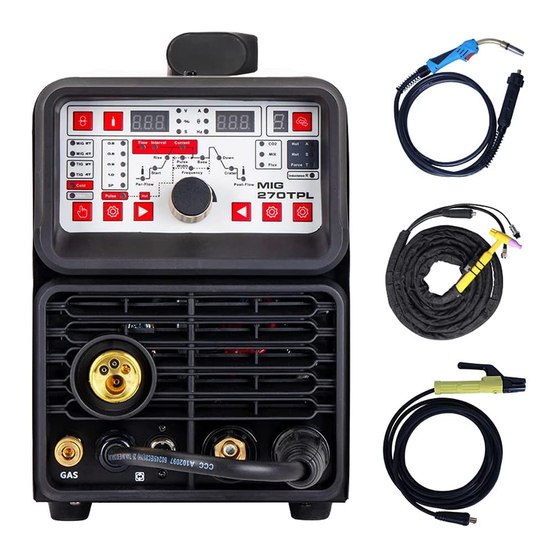
Page 8: Structure Of Welder
4.Structure of welder Display: Welding voltage in MIG, Percentage in TIG, Low temperature time in TIG Gas-check button Wire-check button Indicator for Cold welding in TIG Function Selector: 2T/4T in MIG, 2T/4T in TIG, Cold welding, MMA Indicator for Pulse in TIG Selector: Wire diameter (Synergic mode)/Manual mode in MIG, Pulse in TIG Parameter Selector in TIG Parameter Adjust Knob... -
Page 9: Installation
20. Wire tension adjustment 21. Wire tension arm & support roller 22. Wire input guide 23. Wire drive roller 24. Drive roller retainer 25. Wire spool retainer 26. Spool brake adjustment 27. Torch trigger switch 28. Torch “Euro” connector 29. Workpiece earth clamp 30. - Page 10 5.1.2 Loading wire feeder 5.1.2.1 release the wire feeder tension arm(21) by pivoting the wire feed tension adjuster(20) as pictured below. 5.1.2.2 check the wire drive roller(23) groove matches the selected MIG wire type and size. The drive roller will have two different sized grooves, the size of the groove in use is stamped on the side of the drive roller.
- Page 11 metal, with no corrosion, paint or scale at the contact point 5.1.4 Setup for gas shielded MIG welding operation Note - Gas shielded MIG welding requires a shielding gas supply, gas regulator and gas shielded MIG wire. These accessories are not supplied standard with the RW1500MP. Please contact your local Repco branch for details. 5.1.4.1 Connect the MIG Torch Euro Connector (28) to the torch socket on the front of the welder (11).
- Page 12 Connection of Shield Gas Connect the CO hose, which come from the wire feeder to the copper nozzle of gas bottle. The gas supply system includes the gas bottle, the air regulator and the gas hose, the heater cable should be inserted into the socket of machine’s back, and use the hose clamp to tighten it to prevent leaking or air-in, so that the welding spot is protected.
-
Page 13: Welding Settings Quick Reference Chart
6.Welding settings quick reference chart... - Page 14 Basic welding guide MIG (GMAW/FCAW) Basic Welding Technique Two different welding processes are covered in this section (GMAW and FCAW), with the intention providing the very basic concepts in using the MIG mode of welding, where a welding gun is hand held, and the electrode (welding wire) is fed into a weld puddle, and the arc is shielded by an inert welding grade shielding gas or inert welding grade shielding gas mixture.
- Page 15 Position of MIG Torch The angle of MIG torch to the weld has an effect on the width of the weld. The welding gun should be held at an angle to the weld joint. (See Secondary Adjustment Variables below) Hold the gun so that the welding seam is viewed at all times.
- Page 16 Distance from the MIG Torch Nozzle to the Work Piece The electrode wire stick out from the MIG Torch nozzle should be between 10mm to 20.0mm. This distance may vary depending on the type of joint that is being welded. Travel Speed The speed at which the molten pool travels influences the width of the weld and penetration of the welding run MIG Welding (GMAW) Variables...
- Page 17 Establishing the Arc and Making Weld Beads Before attempting to weld on a finished piece of work, it is recommended that practice welds be made on a sample metal of the same material as that of the finished piece. The easiest welding procedure for the beginner to experiment with MIG welding is the flat position. The equipment is capable of flat, vertical and overhead positions.
-
Page 18: Range Of Welding Current And Voltage In Co2 Welding
7.Range of welding current and voltage in CO welding Short circuit transition Granular transition Wire φ(mm) Voltage (V) Voltage (V) Current(A) Current(A) 40~70 17~19 160~400 25~38 60~100 18~19 200~500 26~40 80~120 18~21 200~600 27~40 -The option of the welding speed The welding quality and productivity should be taken into consideration for the option of welding speed. - Page 19 45~55 80~100 18~19 10~15 40~55 10~15 0~0.5 100~110 19~20 50~55 10~15 0.5~1.0 1.0 or 1.2 110~130 19~20 40~50 10~15 1.0~1.2 1.0 or 1.2 130~150 19~21 40~50 10~15 1.2~1.5 150~170 21~23 Gasless 30~40/20~30 0.5~1.0 0.8/1.0 110~130 14~16 50~60/40~50 1.0~1.2 0.8/1.0 130~150 15~17 60~70/50~60 1.2~1.5...
- Page 20 2.5~3.0 70~100 18~19 50~60 10~15 2.5~3.0 1.0 ~ 1.2 50~60 90~120 18~20 10~15 3.0~3.5 1.0 ~ 1.2 50~60 10~20 100~130 19~20 3.0~3.5 50~60 10~20 1.0 ~ 1.2 120~140 19~21 3.0~4.0 45~55 10~20 1.0 ~ 1.2 130~170 22~22 4.0~4.5 45~55 10~20 200~250 23~26 Gasless...
-
Page 21: Caution
9.CAUTION 1. Working environment ⑴ Welding should be carried out in a relatively dry environment with its humidity of 90% or less. ⑵ The temperature of the working environment should be within -10C to 40C. ⑶ Avoid welding in the open air unless sheltered from sunlight and rain, and never let rain or water infiltrate the machine. ⑷... -
Page 22: Maintenance
10.MAINTENANCE 1. Disconnect input plug or power before maintenance or repair on machine. 2. Be sure input ground wire is properly connect to a ground terminal. 3. Check whether the inner gas-electricity connection is well (esp. the plugs), and tighten the loose connection; if there is oxidization, remove it with sand paper and then re-connect. -
Page 23: Daily Checking
11.DAILY CHECKING To make best use of the machine, daily checking is very important. During the daily checking, please check in the order of torch, wire-feeding vehicle, all kinds of PCB, the gas hole, and so on. Remove the dust or replace some parts if necessary. To maintain the purity of the machine, please use original welding parts. - Page 24 11.2. Welding torch Part Check Remarks 1. Check if the nozzle is fixed firmly Possible gas leakage occurs due to the unfixed nozzle. and distortion of the tip exists. Nozzle 2. Check if there is spatter sticking on Spatter possibly leads to the damage of torch. Use the nozzle.
- Page 25 11.3. Wire feeder Part Check Remarks Pressure 1. Check if the pressure-adjusting handle is The unfixed pressure-adjusting handle leads adjusting fixed and adjusted to the desired position. to the unstable welding output. handle 1. Check if there is dust or spatter inside the Remove the dust.
-
Page 26: Connection Diagram Of The Machine
12.CONNECTION DIAGRAM OF THE MACHINE... -
Page 27: Explosion Drawing
13.EXPLOSION DRAWING power cable front panel wire buckle upper plastic panel solenoid valve knob power switch downward plastic panel upper plastic panel wire buckle downward plastic panel polar conversion line real panel 35-50 quick connector fan support rubber support base plate clapboard fixed beam machine cover...
Need help?
Do you have a question about the MIG-270TPL and is the answer not in the manual?
Questions and answers
In cold welding, does the machine needs gas?
No, the ANDELI MIG-270TPL machine supports gasless welding and is capable of cold welding without requiring gas.
This answer is automatically generated
Какой размер подающего ролика протяжки проволки, что бы купить под порошковую проволку
The wire feeding roller for the ANDELI MIG-270TPL to use with flux-cored wire should have a serrated groove profile. The roller has two different sized grooves, and the correct one should be selected based on the wire size being used.
This answer is automatically generated