
Related Manuals for Keba KeDrive D3-DA BG3


Summary of Contents for Keba KeDrive D3-DA BG3
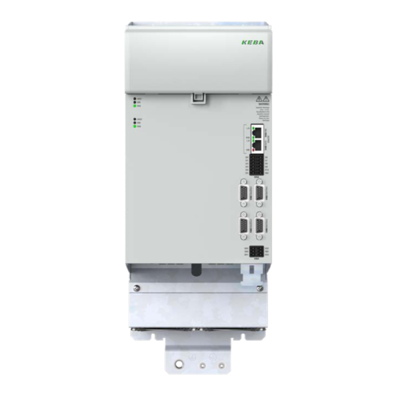
- Page 1 KeDrive D3-DA Axis Controller BG3 and BG4 Operation manual Compact multi-axis system KeDrive D3...
- Page 2 Operation Manual KeDrive D3-DA BG3 and BG4 1804.200B.1-01 Date: 03/2023 Overview, KeDrive D3-DA axis controllers Compact multi-axis system KeDrive D3 KeDrive D3-DA axis controller BG3 KeDrive D3-DA axis controller BG4 Consisting of the KeDrive D3-DP supply unit, the DC-powered KeDrive D3-DA axis...
-
Page 3: Table Of Contents
Digital inputs on X25A (standard functions) ..........40 2.9.1 Directives, standards and regulations ............13 4.7.2 Digital inputs on X26A (safe digital inputs) ..........41 2.9.2 UKCA declaration of conformity ...............13 Operation Manual KeDrive D3-DA BG3 and BG4 1804.200B.1-01 Date: 03/2023 Table of contents Table of contents... - Page 4 Table of contents Table of contents Operation Manual KeDrive D3-DA BG3 and BG4 1804.200B.1-01 Date: 03/2023 Diagnostics .................63 Motor connection ....................41 4.8.1 Motor connection diagram ...............42 Axis status LEDs..................... 63 4.8.2 Motor holding brake monitoring output ........... 45 6.1.1 Flashing code ..................63 4.8.3...
-
Page 5: General
To obtain stated performance features and product characteristics. Prerequisites for usage of the devices from KEBA: KEBA does not accept any liability for injuries, damage or financial losses that result from The documentation on the devices is to be stored so it is legible, accessible at the failure to follow the documentation. -
Page 6: Order Code
24: 24 A BG3 (2 axes) 32: 32 A BG3 (2 axes) 45: 45 A BG3 (1 + 2 axes) On the rating plate for the KeDrive D3-DA BG3 and BG4 you will find the serial number. Rated current 80: 80 A BG3 (1 axis) You can identify the date of manufacture based on the following key. -
Page 7: Brief Description
Size (BG) 3 and size (BG) 4 BG3 and BG4 NOTE Only the KeDrive D3-DA BG3 and BG4 are described in this operation manual. You will find information about the other components of the KeDrive D3 drive NOTE: system in the related operation manuals. -
Page 8: Scope Of Supply
General General Operation Manual KeDrive D3-DA BG3 and BG4 1804.200B.1-01 Date: 03/2023 Scope of supply 1.11 Support The scope of supply includes: Address: KEBA Industrial Automation Germany GmbH Gewerbestrasse 5-9 KeDrive D3-DA axis controllers BG3 and BG4 35633 Lahnau Ready-made connection cable for EtherCAT... -
Page 9: Safety
(capacitor charge). Therefore check there is no electrical power in the device! See also the warning label on the front panel on the device. • Rotating parts • Automatically starting drives. • Hot components and surfaces Operation Manual KeDrive D3-DA BG3 and BG4 1804.200B.1-01 Date: 03/2023 Safety Safety... -
Page 10: General Safety Instructions And Warnings
Safety Safety Operation Manual KeDrive D3-DA BG3 and BG4 1804.200B.1-01 Date: 03/2023 General safety instructions and warnings NOTE: The pictograms may also be used on their own with the signal word, e.g. in the connection diagrams, however they have the same function as in the... -
Page 11: Misuse
Not approved for usage outside a switch cabinet. Not approved for the generation of high-frequency onboard For information about laws, standards and directives applied by KEBA, refer to the networks for which the devices are not designed. declaration of conformity. -
Page 12: Declaration Of Conformity
Great Britain (England, Wales and Scotland). Authorised representative is: KEBA Ltd. Aston Court Frederick Place Kingsmead Business Park High Wycombe HP11 1JU Authorised person to compile the technical file is Ian Hanton, KEBA Ltd. -
Page 13: Directives, Standards And Regulations
Substances in Electrical and Electronic Equipment Electrical and Electronic Equipment Regulations 2012 2.9.2 UKCA declaration of conformity The declaration of conformity for the product can be requested from KEBA Industrial Automation Germany GmbH. Operation Manual KeDrive D3-DA BG3 and BG4 1804.200B.1-01 Date: 03/2023 Safety... - Page 14 Safety Safety Operation Manual KeDrive D3-DA BG3 and BG4 1804.200B.1-01 Date: 03/2023...
-
Page 15: Mechanical Installation
(see Table A.1). The root mean square of the active power for a load cycle is manuals for the other devices (supply unit, controller, etc.) are also followed. defined as the total active power. Operation Manual KeDrive D3-DA BG3 and BG4 1804.200B.1-01 Date: 03/2023 Mechanical installation... -
Page 16: Mounting Clearances
• The minimum clearances stated in the figure below apply to all devices (KeDrive D3-DU, KeDrive D3-DP BG3 and BG4 and KeDrive D3-DA BG3 and BG4). • The clearance above the devices is important to prevent the build-up of heat. The clearance underneath and at the front is necessary to permit correct cable laying. -
Page 17: Cooling Of The Devices With Air Cooling
It is imperative the min. mounting clearances above and below are met for thermal reasons. Depending on the connection cables used (mains cable/ motor cable), the mounting clearances may increase significantly due to the bending radii necessary. Operation Manual KeDrive D3-DA BG3 and BG4 1804.200B.1-01 Date: 03/2023 Mechanical installation Mechanical installation... -
Page 18: Installation Of The Devices With Air Cooling
Mechanical installation Mechanical installation Operation Manual KeDrive D3-DA BG3 and BG4 1804.200B.1-01 Date: 03/2023 Installation of the devices with air cooling Step Action Comment Arrange the devices on the backing plate as per Figure 3.1. Please also provide enough space to the left of the This action is necessary to be able to supply unit for the controller. -
Page 19: Dimensions (Housing With Heat Sink)
H (height) T/T1 (depth) 251 / 222 251 / 222 Mounting holes Figure 3.5 Dimensional drawing, KeDrive D3-DA BG3 (example 1 x 45 A) Screws 4 x M4 4 x M4 All dimensions in mm 1) Without terminals and connectors Table 3.1 Table of dimensions KeDrive D3-DA BG3 and BG4 wall mounting... -
Page 20: Installation Of The Devices With Liquid Cooling
You will find further notes on the liquid cooling in chap. A.9. You will find the next steps for the electrical installation in “4 Electrical installation”. Screws 5 x M4 9 x M4 All dimensions in mm Table 3.2 Table of dimensions KeDrive D3-DA BG3 and BG4 liquid cooling... - Page 21 Figure 3.7 Dimensional drawing, D3-DA 3xx axis controller BG3 (example 1x 80 A) Cø G 3/8 (15 tief) Figure 3.8 Dimensional drawing, D3-DA 3xx axis controller BG4 (example 1x 250 A) Operation Manual KeDrive D3-DA BG3 and BG4 1804.200B.1-01 Date: 03/2023 Mechanical installation Mechanical installation...
-
Page 22: Cooling Circuit Connection
Mechanical installation Mechanical installation Operation Manual KeDrive D3-DA BG3 and BG4 1804.200B.1-01 Date: 03/2023 Cooling circuit connection The KeDrive D3-DA device has a capacity of up to 0.5 l of coolant depending on the size. After the disconnection of the connections, liquid may be left in the device and escape if the device is tipped. -
Page 23: Kedrive D3-Da Configurations (Examples)
1 controller, 1 supply unit, 1 capacitance module, 5 double-axis controllers BG3 and 1 single-axis controller BG3 8 bus users with 11 axes. Figure 3.11 KeDrive D3-DA BG3, all components Note: 1 controller, 1 supply unit, 1 capacitance module, 1 single-axis controller BG4, 3... - Page 24 Operation Manual KeDrive D3-DA BG3 and BG4 1804.200B.1-01 Date: 03/2023...
-
Page 25: Electrical Installation
To connect KEBA servomotors we recommend the usage of ready- NOTE: made motor and encoder cables from KEBA, as all EMC tests have been During the installation of the axis controller in a KeDrive D3 system, it is undertaken successfully with these cables. - Page 26 The wiring must be directly connected to the respective coil. Any switched inductance should be at least 0.2 m away from the process- controlled assemblies. If you require further detailed information about installation, you should consult the KEBA Helpline, see chapter 1.11. Figure 4.1 Example shield connection, control connections...
-
Page 27: Overview Of The Connections
See Chapter 4.6.1 24 V DC 24 V DC busbars (control supply) In the following you will find two layouts for the KeDrive D3-DA BG3 and BG4 with the corresponding positions of connectors and terminals. See Chapter 4.6.2 DC link DC link busbars (power supply) See Chapter 6.1... - Page 28 Electrical installation Electrical installation Operation Manual KeDrive D3-DA BG3 and BG4 1804.200B.1-01 Date: 03/2023 24 V DC 24 V DC DC-Link DC-Link Status Status (Axis 1) (Axis 1) X40A X40A X40B X40B X25A X25A (X31A) X48A (X31A) X48A X48B X48B...
- Page 29 Connection for temperature monitoring, X31A (TEMP/BRAKE) motor winding/motor brake Connection for protective earth See Chapter 4.4 conductor/ earthing Table 4.4 Key to the layout, KeDrive D3-DA BG4 Operation Manual KeDrive D3-DA BG3 and BG4 1804.200B.1-01 Date: 03/2023 Electrical installation Electrical installation...
-
Page 30: Single-Axis Controller
Electrical installation Electrical installation Operation Manual KeDrive D3-DA BG3 and BG4 1804.200B.1-01 Date: 03/2023 4.3.1 Single-axis controller Abbreviation Designation Details Can also be used as Ethernet interface for PC with DriveManager. For X40A EtherCAT IN, input, field bus Axis 1... - Page 31 1) If connected to the encoder connector, the motor temperature sensor must be provided with reinforced insulation as per DIN EN 61800-5-1 in relation to the motor winding. 2) Typ. 5.25 V, max 5.4 V, 250 mA max. 3) Alternative power supply for certain encoder types 4) Possible from firmware release 2.10-03 Operation Manual KeDrive D3-DA BG3 and BG4 1804.200B.1-01 Date: 03/2023 Electrical installation Electrical installation...
-
Page 32: Double-Axis Controller
Electrical installation Electrical installation Operation Manual KeDrive D3-DA BG3 and BG4 1804.200B.1-01 Date: 03/2023 4.3.2 Double-axis controller Abbreviation Designation Details Can also be used as Ethernet interface for PC with DriveManager Axis 1 X40A EtherCAT IN, input, field bus 5. For information about activating... - Page 33 2) Typ. 5.25 V, max 5.4 V, 250 mA max. 3) Alternative power supply for certain encoder types 4) Possible from firmware release 2.10-03 5) From revision state F Operation Manual KeDrive D3-DA BG3 and BG4 1804.200B.1-01 Date: 03/2023 Electrical installation Electrical installation...
- Page 34 Electrical installation Electrical installation Operation Manual KeDrive D3-DA BG3 and BG4 1804.200B.1-01 Date: 03/2023 Double-axis controller encoder axis 2 SinCos SinCos Fig. EnDat / SSI Hiperface BISS Resolver Fig. Resolver and TTL and TTL A− REFCOS S3 / COS− (A−) A−...
-
Page 35: Protective Earth Conductor Connection
Q however at least 10 mm (Cu) 16 mm < Q ≤ 35 mm 16 mm Q > 35 mm Table 4.13 Protective earth conductor cross-section Operation Manual KeDrive D3-DA BG3 and BG4 1804.200B.1-01 Date: 03/2023 Electrical installation Electrical installation... -
Page 36: Connection Principle
Electrical installation Electrical installation Operation Manual KeDrive D3-DA BG3 and BG4 1804.200B.1-01 Date: 03/2023 Electrical isolation concept 4.4.2 Connection principle The control terminals are designed as protective extra low voltage (PELV) circuits and Netz/Line must only be operated with such PELV voltages, as per the relevant specification. This aspect provides reliable protection against electric shock. -
Page 37: Connection Of The Supply Voltages
Make sure that all connections have good contact and are sufficiently secure that they cannot (6) Mains choke (accessory) (17) Backing plate earthing come loose. If connection elements are used that do not meet the requirements, KEBA does (7) Mains supply (DC link) (18) EtherCAT connection not provide any guarantee for stable, reliable operation. -
Page 38: 24 V Control Supply
Electrical installation Electrical installation Operation Manual KeDrive D3-DA BG3 and BG4 1804.200B.1-01 Date: 03/2023 4.6.1 24 V control supply 4.6.2 Power supply The supply units KeDrive D3-DP BG3 and BG4 need an external 24 V DC power supply The supply voltage for the axis controllers is supplied by the supply unit KeDrive D3-DP unit for the 24 V DC supply (see Figure 4.9). -
Page 39: Overview Of Busbars In The Group
The multi-axis system is only allowed to be operated with the cover on the busbars closed! It is also important that the side covers (A) are fitted. Both provide protection against touching bare and live parts. Operation Manual KeDrive D3-DA BG3 and BG4 1804.200B.1-01 Date: 03/2023 Electrical installation... -
Page 40: Digital Inputs On X25A (Standard Functions)
Electrical installation Electrical installation Operation Manual KeDrive D3-DA BG3 and BG4 1804.200B.1-01 Date: 03/2023 4.7.1 Digital inputs on X25A (standard functions) Electrical Des. Term. Specification isolation The digital inputs are provided for axis-related tasks, e.g. hardware limit switches. They DI00 can be programmed individually via the EtherCAT bus system. -
Page 41: Digital Inputs On X26A (Safe Digital Inputs)
Avoid loop currents in the wiring. If high currents flow via the ground terminals, high-impedance isolation from the device ground is possible. This can result in the malfunction of the drive. Operation Manual KeDrive D3-DA BG3 and BG4 1804.200B.1-01 Date: 03/2023 Electrical installation... -
Page 42: Motor Connection Diagram
Motor current • Ensure the drive is brought safely to a standstill. The temperature sensor connection is shown in the version with "standard encoder interface". Figure 4.12 Connection of one servomotor with motor holding brake, KeDrive D3-DA BG3... - Page 43 Holding brake (+) Motor 1 The temperature sensor connection is shown in the version with "standard encoder interface". Figure 4.13 Connection of two servomotors with motor holding brake, KeDrive D3-DA BG3 Operation Manual KeDrive D3-DA BG3 and BG4 1804.200B.1-01 Date: 03/2023...
- Page 44 Electrical installation Electrical installation Operation Manual KeDrive D3-DA BG3 and BG4 1804.200B.1-01 Date: 03/2023 Recommended connection of the motor holding brake up to max. 2 A brake current. Hiperface DSL- Hiperface DSL+ The two-wire connection for the encoder is U V W...
-
Page 45: Motor Holding Brake Monitoring Output
Connection for motor PE M6 or M10 screw with serrated M6 max. 4.8 Nm washer for ring lug M10 max. 22 Nm Table 4.18 Specification for motor connections Operation Manual KeDrive D3-DA BG3 and BG4 1804.200B.1-01 Date: 03/2023 Electrical installation Electrical installation... -
Page 46: Switching In The Motor Cable
Electrical installation Electrical installation Operation Manual KeDrive D3-DA BG3 and BG4 1804.200B.1-01 Date: 03/2023 4.8.4 Switching in the motor cable CAUTION! Damage to the device due to switching in the motor cable! Carelessness can cause damage to the device Switching in the motor cable must take place with the power switched off and the power stage... -
Page 47: Encoder Connections
Contents ID no. Format To connect the LSP, LSD, LSN, LST and DMS2 synchronous motors, please use the ready-made motor and encoder cable from KEBA, see also A.8. KeDrive D3 Overview with notes on ordering and project planning information System 1404.205B.x... -
Page 48: Connection For High-Resolution Encoders (X48A And X48C)
Axis 1 Axis 1 4.9.2 Connection for high-resolution encoders (X48A and NOTE: The usage of encoders not included in the range supplied by KEBA requires X48C) special approval from KEBA. Axis 2 Axis 2 The maximum signal input frequency is 500 kHz. -
Page 49: Connection For Additional Encoder (X48B And X48D)
KeStudio DriveManager (if you have any questions on this topic, please contact us). NOTE: The usage of encoders not included in the range supplied by KEBA requires NOTE: special approval from KEBA. EtherCAT® is specified in IEC61158 and IEC61784. You will find general information about EtherCAT®... - Page 50 Electrical installation Electrical installation Operation Manual KeDrive D3-DA BG3 and BG4 1804.200B.1-01 Date: 03/2023 Connection example Technical specification: Transfer rate 10/100 Mbits/s BASE-T Statusanzeige: tatusanzeige: Transfer profile IEEE802.3-compliant Shielding of the connector over the entire connector length Axis 1 Axis 1...
- Page 51 A communication group is allowed to consist of a maximum of 9 bus users. Motor1 Motor2 230 V AC/ 24 V DC L1 L2 L3 Figure 4.22 Connection example (schematic depiction) Operation Manual KeDrive D3-DA BG3 and BG4 1804.200B.1-01 Date: 03/2023 Electrical installation Electrical installation...
- Page 52 Electrical installation Electrical installation Operation Manual KeDrive D3-DA BG3 and BG4 1804.200B.1-01 Date: 03/2023...
-
Page 53: Commissioning
If Ethernet data (TCP/IP) are also to be sent in an EtherCAT® network, the EtherCAT® then act as TCP/IP connections. master must support the function Ethernet-over-EtherCAT® (EoE) to be able to tunnel Ethernet data to the axis controllers Operation Manual KeDrive D3-DA BG3 and BG4 1804.200B.1-01 Date: 03/2023 Commissioning Commissioning... -
Page 54: Procedure For Activating The Service/Diagnostics Mode
Commissioning Commissioning Operation Manual KeDrive D3-DA BG3 and BG4 1804.200B.1-01 Date: 03/2023 5.1.3 Procedure for activating the service/diagnostics mode: NOTE: The function described in the following is available on KeDrive D3-DA axis controllers from firmware version V2.20. The service and diagnostics mode is CC-Master activated for all axes in the axis group. - Page 55 The order designation is XW 021-xxx where xxx specifies the length of the cabled (xxx * 10 cm). Two axis groups (two separate cross-communication groups) are shown in this figure. Operation Manual KeDrive D3-DA BG3 and BG4 1804.200B.1-01 Date: 03/2023 Commissioning Commissioning...
-
Page 56: Exiting The Service/Diagnostics Mode
Commissioning Commissioning Operation Manual KeDrive D3-DA BG3 and BG4 1804.200B.1-01 Date: 03/2023 5.1.4 Exiting the service/diagnostics mode: 1. Service interface on the supply unit in the service and diagnostics After the conclusion of the commissioning, the service and diagnostics mode must be... - Page 57 The interface switchover selected is again signalled by the yellow LEDs flashing quickly (0.1 s/0.1 s) during the next power-up. NOTE: As delivered the KeDrive D3-DA have the default IP address: 192.168.39.5 Operation Manual KeDrive D3-DA BG3 and BG4 1804.200B.1-01 Date: 03/2023 Commissioning Commissioning...
-
Page 58: Initial Commissioning Of The Axis Controller
Settings for the supply unit (see also KeDrive D3-DP Supply Unit Operation Manual • It is imperative attention is paid to the limitations of the movement range. You are (ID no. 1804.201B.x)) responsible for a safe process. KEBA will not accept liability for any damage that occurs KeStudio DriveManager Function... -
Page 59: Controlling Drive Using Kestudio Drivemanager
The data sets for the motor range DMS2 are saved in the encoders and are loaded directly from there. NOTE: You will find a detailed description of KeStudio DriveManager and its configu- ration in the KeStudio DriveManager help. Operation Manual KeDrive D3-DA BG3 and BG4 1804.200B.1-01 Date: 03/2023 Commissioning Commissioning... -
Page 60: Serial Commissioning
Commissioning Commissioning Operation Manual KeDrive D3-DA BG3 and BG4 1804.200B.1-01 Date: 03/2023 KeStudio DriveManager Function CAUTION! Damage to the motor due to incorrect operation during motor test run! Open manual mode window Carelessness can result in significant damage to the motor or machine. -
Page 61: Standard Operation On The Kedrive D3-Du Controller
− ETG1000_6_S_R_V1i0i2_EcatALProtocols In addition, as the communication master, the controller takes on the task of routing Figure 5.9 Advanced EtherCAT master settings Ethernet protocols between the bus users. Operation Manual KeDrive D3-DA BG3 and BG4 1804.200B.1-01 Date: 03/2023 Commissioning Commissioning... - Page 62 Commissioning Commissioning Operation Manual KeDrive D3-DA BG3 and BG4 1804.200B.1-01 Date: 03/2023 Step 2: Assignment of the virtual IP address for the EtherCAT slave Step 3: Establishment of communication with KeStudio DriveManager The virtual IP address configured in the previous step is to be used for the EoE communication.
-
Page 63: Diagnostics
= LED off = LED flashing Figure 6.1 Status LEDs Table 6.1 LED messages for the service/ diagnostics mode X48C X48A X48D X48B Operation Manual KeDrive D3-DA BG3 and BG4 1804.200B.1-01 Date: 03/2023 SDI00 SDI02 X26A SDI01 SDI03 Diagnostics... -
Page 64: Status And Error Indication In Kestudio Drivemanager
Diagnostics Diagnostics Operation Manual KeDrive D3-DA BG3 and BG4 1804.200B.1-01 Date: 03/2023 Status and error indication in If an error occurs, a "pop-up" window appears immediately with more detailed informa- tion about the actual error. KeStudio DriveManager Click the "Device status" button in the header for the DM5 to open the "Device status"... - Page 65 In the new window that opens you will find the history for the errors and warnings. NOTE: You will find further information about parameter 100 in the device help KeDrive D3-DA (1404.209B.x). Figure 6.5 Error history, error information mask Operation Manual KeDrive D3-DA BG3 and BG4 1804.200B.1-01 Date: 03/2023 Diagnostics Diagnostics...
- Page 66 Operation Manual KeDrive D3-DA BG3 and BG4 1804.200B.1-01 Date: 03/2023...
-
Page 67: Safety Design Variants
EN ISO 13849-1 "PL e / cat 4" and EN 61508 / EN 62061 "SIL CL 3". NOTE: You will find all further information in the document "Model Description SDC" (ID no. 1404.206B.x). Operation Manual KeDrive D3-DA BG3 and BG4 1804.200B.1-01 Date: 03/2023 Safety design variants Safety design variants... - Page 68 Safety design variants Safety design variants Operation Manual KeDrive D3-DA BG3 and BG4 1804.200B.1-01 Date: 03/2023...
-
Page 69: Appendix
1) At 4 kHz, 400 V AC power feed via supply unit, for other currents see following pages, 2) Liquid-cooled version Table A.1 Technical data, KeDrive D3-DA axis controllers BG3 and BG4 Operation Manual KeDrive D3-DA BG3 and BG4 1804.200B.1-01 Date: 03/2023... -
Page 70: Power Section Current Data, 24 A To 210 A Controller, Air-Cooled
Appendix Appendix Operation Manual KeDrive D3-DA BG3 and BG4 1804.200B.1-01 Date: 03/2023 Power section current data, 24 A to 210 A controller, air-cooled D3-DA 320/A-24xx D3-DA 320/A-32xx D3-DA 310/A-45xx D3-DA 320/A-45xx D3-DA 310/A-80xx D3-DA 310/A-A3xx D3-DA 310/A-B1xx Unit Mains (BG3) - Page 71 Remarks: Current data per axis in the axis controller 400/480 V AC refer to the feed voltage for the supply unit, firmware release V003.30.00 Table A.2 Current data, KeDrive D3-DA axis controllers BG3 and BG4, air-cooled Operation Manual KeDrive D3-DA BG3 and BG4 1804.200B.1-01 Date: 03/2023...
-
Page 72: Power Section Current Data, 24 A To 300 A Controller, Liquid-Cooled
Appendix Appendix Operation Manual KeDrive D3-DA BG3 and BG4 1804.200B.1-01 Date: 03/2023 Power section current data, 24 A to 300 A controller, liquid-cooled D3-DA D3-DA D3-DA D3-DA D3-DA D3-DA D3-DA D3-DA Unit 320/C-24xx 320/C-32xx 310/C-45xx 320/C-45xx 310/C-80xx 310/C-A3xx 310/C-B1xx 310/C-C0xx... - Page 73 Remarks: Current data per axis in the axis controller 400/480 V AC relate to the feed voltage for the supply unit, firmware release V003.30.00 Table A.3 Current data, KeDrive D3-DA axis controllers BG3 and BG4, liquid-cooled Operation Manual KeDrive D3-DA BG3 and BG4 1804.200B.1-01 Date: 03/2023...
-
Page 74: Ambient Conditions
Appendix Appendix Operation Manual KeDrive D3-DA BG3 and BG4 1804.200B.1-01 Date: 03/2023 Ambient conditions NOTE: The climatic conditions apply to the device. For this reason they must also be met in the switch cabinet. Ambient conditions KeDrive D3-DA axis controllers BG3 and BG4... -
Page 75: Power Reduction At T
/ system, then the scope of the standard is to be checked for the complete machine / system. NOTE: Until the type test is completed, all technical data are only calculated values and not assured characteristics. Operation Manual KeDrive D3-DA BG3 and BG4 1804.200B.1-01 Date: 03/2023 Appendix Appendix... -
Page 76: Accessories
Appendix Appendix Operation Manual KeDrive D3-DA BG3 and BG4 1804.200B.1-01 Date: 03/2023 Accessories Connection system We have supplemented the KeDrive D3 system with comprehensive accessories. We offer ready-made cables in various lengths for the connection of servomotors in the Important components are, e.g.: product ranges DMS2, LST, LSN and LSP to the KeDrive D3-DA axis controllers. -
Page 77: Hydrological Data For The Liquid Cooling
10 °K below the ambient temperature to prevent condensation on the heat sink. Chiller material and the Aluminium connections Table A.8 Requirements, liquid cooling Operation Manual KeDrive D3-DA BG3 and BG4 1804.200B.1-01 Date: 03/2023 Appendix Appendix... - Page 78 Appendix Appendix Operation Manual KeDrive D3-DA BG3 and BG4 1804.200B.1-01 Date: 03/2023...
-
Page 79: Glossary
Configurations ......................23 EMC product standard ....................25 Connection diagram ....................51 EN^ISO 13849 ......................74 Motor ........................42 EN 60664 ........................15 Connections BG3 ....................... 27 EN 61800 ......................45, 74 Operation Manual KeDrive D3-DA BG3 and BG4 1804.200B.1-01 Date: 03/2023 Glossary Glossary... - Page 80 Glossary Glossary Operation Manual KeDrive D3-DA BG3 and BG4 1804.200B.1-01 Date: 03/2023 Encoder ........................48 EnDat ........................48 KeDrive D3 SinCos ....................31, 33, 34, 48 Documentation (overview) ..................5 SSI interface ......................48 KeDrive D3 DU Encoder connection ....................47 Configuration ......................
- Page 81 SD0 ..........................67 Warnings ........................10 SDC ........................... 67 Sequence ........................15 Serial commissioning ....................60 Zero pulse ........................48 Serial number ....................... 6 Service/diagnostics mode ................30, 32, 54 Operation Manual KeDrive D3-DA BG3 and BG4 1804.200B.1-01 Date: 03/2023 Glossary Glossary...
- Page 82 Glossary Glossary Operation Manual KeDrive D3-DA BG3 and BG4 1804.200B.1-01 Date: 03/2023...
- Page 83 Operation Manual KeDrive D3-DA BG3 and BG4 1804.200B.1-01 Date: 03/2023...
- Page 84 Czech Republic • Turkey • USA Copyright © 2023 KEBA All rights reserved. All content of the documentation, in particular the text, photographs and graphics it contains are protected by copyright. The copyright lies, unless otherwise expressly stated, with KEBA Industrial Automation Germany GmbH.
Need help?
Do you have a question about the KeDrive D3-DA BG3 and is the answer not in the manual?
Questions and answers