
Related Manuals for Keba KeContact M20


Summary of Contents for Keba KeContact M20
- Page 1 KeContact Expanded charging management Operating manual V 1.02 Translation of the original instructions...
- Page 2 Specifications are subject to change due to further technical developments. Details presented may be subject to correction. All rights reserved. Reindlstraße 51, 4040 Linz, Austria, www.keba.com/emobility KEBA Energy Automation GmbH +43 732 7090-0, +43 732 7309-10, kecontact@keba.com For information about KEBA and our subsidiaries please look at www.keba.com.
-
Page 3: Table Of Contents
ESD information....................Inserting the SIM card..................Space requirement................... Installation in the control cabinet..............Wall installation ....................Removing......................Connections and wiring.................... Power supply ....................USB port ......................Ethernet interface..................... Graphic interface....................Antenna......................Configuration ......................Enabling the DHCP server................V1.02 © KEBA 2022... - Page 4 General ......................11.2 Power supply ....................11.3 Ambient conditions................... 11.4 Interfaces Embedded PC................. 11.5 LTE antenna ....................11.6 Dimensions, weight..................12 EU directives and standards ..................13 UKCA .......................... 14 EC Declaration of Conformity .................. Index ........................... V1.02 © KEBA 2022...
-
Page 5: Introduction
Introduction This document describes an expanded charging network with the following devices: ● KeContact M20 master device (embedded PC with power adapter and LTE antenna) ● Compatible client devices (P30 c-series) The device variant can be read off based on the product designation on the type plate. -
Page 6: Purpose Of The Document
Purpose of the document This document describes the installation and configuration of the expanded KeContact M20 functions. This includes the description of settings in the web interface. WARNING! Risk of electric shock to persons! In addition to this document, all information in the description of the power adapter, which is in the power adapter packaging, must be observed. -
Page 7: Warranty
Introduction Warranty Only general maintenance work that is expressly permitted by KEBA may be performed. Any other tampering to the device will result in a loss of the war- ranty claim. Notes on this document The manual is part of the product. It is to be retained over the entire life cycle of the product and should be forwarded to any subsequent owners or users of the product. -
Page 8: System Overview
System overview System overview The KeContact M20 enables control of multiple charging stations. The con- nection is established over the IT network (switch/router). This makes charg- ing with an intelligent load management possible. In combination with an up- stream electricity meter, the entire charging network can be controlled dy- namically (Modbus TCP). - Page 9 (number depending on variant) in max. 15 clusters can be connected with each other. Fig. 2-2: System overview with cluster (example) ... Cluster 1 ... Cluster 2 ... Cluster 3 The following chapters describe which network interfaces are provided and how to set up a network. V1.02 © KEBA 2022...
-
Page 10: Network Interfaces
Information WLAN stick (WLAN access point / WLAN hotspot) ● The connection of a WLAN stick to the KeContact M20 is fundamentally possible, but not recommended. Use at your own risk. In case of prob- lems, troubleshooting is not assisted by the manufacturer. - Page 11 2.1.1 The master can be connected to a router via the integrated LAN interface. The router provides a connection to an OCPP backend over the Internet..KeContact M20 ... Router ... Internet ... OCPP backend Connection: Ethernet1 connection Via the LAN interface, the master can also be connected to other client charging stations, which creates a charging network.
-
Page 12: Structure Of A Local Charging Network
System overview 2.1.2 Mobile network KeContact M20 has a mobile communications module. It enables a connec- tion to a OCPP backend via the mobile network. The mobile communications provider may charge additional fees (depending on the tariff) for running data transmissions. - Page 13 System overview Fig. 2-5: Connection via router or switch ... Router/Switch ... KeContact M20 (master) ... P30 c-series (client) Using a router For a network connection using a router, the router automatically provides the functionality of a DHCP server in most cases.
- Page 14 Transfer of the software update Within the network (Bootps) Transfer of the software update Within the network (Bootps) Transfer of the software update Within the network (Bootps) Transfer of the software update Within the network (Bootps) V1.02 © KEBA 2022...
-
Page 15: Description
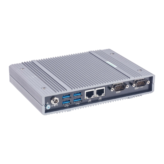
... Power button ... LTE diversity antenna ... LTE main antenna *) Connection nonfunctional Rear view Fig. 3-7: Rear view of embedded PC ... Ground (GND) ... DC-In ... USB ... Ethernet (LAN) ... COM* *) Connection nonfunctional V1.02 © KEBA 2022... -
Page 16: Type Plate
... UKCA marking (currently not yet available) Information The CE marking of KEBA Energy Automation GmbH refers exclusively to the installation of the LTE modem and the SSD as well as the composition of the system components. Accessories / Spare parts... -
Page 17: Displays And Operating Elements
Status LED Description Dark No SSD/USB activity Flashing blue SSD/USB activity Power button The power button on the front of the KeContact M20 is backed by a lighting ring. Description Dark No supply voltage Green Device ready for operation Reset button Pressing the reset button on the front triggers a reset of the KeContact M20. -
Page 18: Mounting And Installation Instructions
Mounting and installation instructions Mounting and installation instructions General instructions To protect the KeContact M20 from unauthorized access, theft, vandalism and incorrect configurations, the device must be installed in a lockable envi- ronment (e.g. lockable control cabinet). WARNING! Risk of electric shock to persons! ●... -
Page 19: Inserting The Sim Card
● Adhere to the ESD information in the chapter "5.2 ESD information". The slot for the SIM card is located inside the KeContact M20. Tools re- quired: ● Phillips screwdriver PH1 (not included in the scope of delivery) ●... - Page 20 3) Tilt the circuit board upward at an angle (1) and pull it out the front (2). 4) Unlock the SIM card slot by sliding the cover back. 5) Tilt the slot cover back 6) Insert the SIM card. Ensure the correct position. 7) Close the cover again. V1.02 © KEBA 2022...
- Page 21 11) Set the lower housing cover on the housing and mount it with screws (max. torque of 0.59 Nm, tolerance ±0.05 Nm). The SIM card is inserted. Information The access data of the mobile network provider must be entered in the web interface (configuration). V1.02 © KEBA 2022...
-
Page 22: Space Requirement
Fig. 5-9: Space requirement (dimensions in mm) for control cabinet installation The specifications are minimum distances. If a USB stick is used in opera- tion, more space may need to be taken into account. Fig. 5-10: Space requirement (in mm) for wall installation V1.02 © KEBA 2022... -
Page 23: Installation In The Control Cabinet
● The SIM card may need to be installed before the mounting is done. Otherwise, installation is no longer possible. The KeContact M20 can be mounted on a top hat rail. The mounting pack- age includes two brackets (one has a shorter depth) and a mounting clip. - Page 24 Proceed as follows to mount the KeContact M20 on the top hat rail: 1) Unscrew the M3 screws on the side of the housing. 2) Secure the short bracket (2) on the KeContact M20 with two M3 screws (max. torque of 0.59 Nm, tolerance ±0.05 Nm).
-
Page 25: Wall Installation
The four screw holes are located on the underside of the KeContact M20. To install the KeContact M20 on the wall, proceed as follows: 1) Unscrew the M3 screws on the underside of the housing. 2) Secure the two wall brackets (1) on the KeContact M20 with four M3 screws. V1.02... -
Page 26: Removing
Mounting and installation instructions 3) The KeContact M20 can be installed at various distances from the wall using the predrilled screw holes. 4) Install the KeContact M20 on the wall. The KeContact M20 is installed on the wall. Removing Dismantling from the top hat rail Tools required: ●... -
Page 27: Connections And Wiring
Connections and wiring Power supply The KeContact M20 may only be supplied using the power adapter included in the scope of delivery (in the control cabinet) using the DC-In jack. The primary supply of the power adapter is the responsibility of the respec- tive electrician (power connection line not included in the scope of delivery). -
Page 28: Ethernet Interface
Bidirectional MX0- Bidirectional MX1+ Bidirectional MX2+ Bidirectional MX2- Bidirectional MX1- Bidirectional MX3+ Bidirectional MX3- Bidirectional Graphic interface The KeContact M20 features a VGA and HDMI/DP combo connector. Information This interface is not currently approved for use. V1.02 © KEBA 2022... -
Page 29: Antenna
25 cm away from people. Mounting the antenna directly on the device To mount the antenna, proceed as follows: 1) Switch off devices connected to the KeContact M20 and disconnect their power cables. 2) Tighten the antenna (2) at the antenna connection (1). - Page 30 5) Use the washer and locknut (included in the scope of delivery) to fasten the antenna on the inside of the control cabinet (max. 5 Nm). 6) Tighten the antenna cable at the two antenna connections. The antenna has been installed. V1.02 © KEBA 2022...
-
Page 31: Configuration
Read out configuration To read out the configuration, proceed as follows: 1) Plug the USB stick into the KeContact M20. It must be ready for opera- tion and already configured. 2) Transfer of the configuration is started automatically. The status LED also flashes and soft audible signals are emitted at longer intervals. -
Page 32: Configuration In Series Via Usb Stick
To import the configuration to the desired KeContact M20, proceed as fol- lows: 1) Plug the USB stick into the KeContact M20. It must be ready for opera- tion and already configured. 2) Transfer of the configuration is started automatically. The status LED also flashes and soft audible signals are emitted at longer intervals. - Page 33 Importing configuration 7.2.1 Create configuration If this has not yet been done, a first KeContact M20 must be configured with the desired settings. These settings serve as the basis for the configuration of additional KeContact M20. The easiest way to configure the KeContact M20 is via the web interface. On the graphical user interface the available settings and selection fields are provided with short explanations.
- Page 34 To import the configuration to the desired KeContact M20, proceed as fol- lows: 1) Plug the USB stick into the KeContact M20. It must be ready for opera- tion and already configured. 2) Transfer of the configuration is started automatically. The status LED also flashes and soft audible signals are emitted at longer intervals.
- Page 35 Configuration 3) After the transfer is finished (approx. 1-2 minutes), the status LED goes out and an audible signal sounds. 4) Remove the USB stick. 5) Restart the KeContact M20. The configuration has been imported. V1.02 © KEBA 2022...
-
Page 36: Web Interface
The con- figuration for the entire charging network takes place via the web interface of the KeContact M20 (master). The actual size of the web interface may differ depending on the device vari- ant. -
Page 37: Main Menu
System ● Configuration 8.1.1 Status The page is divided into the following areas: Overview Here, basic information about all charging stations in the charging network is displayed (such as serial number, IP address, operating state, etc.). V1.02 © KEBA 2022... - Page 38 *.csv 8.1.4 Charging Network The configuration of the charging network is carried out in this area. The area offers the following options: ● No. of charging stations ● Charging network settings ● Cluster V1.02 © KEBA 2022...
- Page 39 "out of operation" mode. 8.1.5 System The area offers the following options: ● Software update ● Logging ● DSW settings ● Factory data reset V1.02 © KEBA 2022...
- Page 40 For an encrypted connection, certificates can be imported in *.pfx format. A connection to the web interface can be encrypted. The following certificates are available: WebUI certificates Certificate Purpose Https WebUI Encrypted connection to the web interface Restart system The master can be restarted with this button. V1.02 © KEBA 2022...
- Page 41 All the necessary configurations for using a proxy server can be found in this part. OCPP All the necessary configurations for connecting to an OCPP backend can be found in this part. The displayed configuration options vary depending on the selected transmission type (SOAP or JSON). V1.02 © KEBA 2022...
-
Page 42: User Menu
● User settings: Settings and changes to the currently logged in user ● Logout: Logout of the currently logged in user 8.2.1 User settings In this area, changes to the following user settings can be made: V1.02 © KEBA 2022... - Page 43 If you forget the web interface password, you can reset it using the displayed recovery key. The recovery key can also be found on the configuration label. Information It is essential to keep the recovery key in a secure place for the entire life of the product! V1.02 © KEBA 2022...
-
Page 44: Functions
Assignment via UDP connection ● Readout of an external meter using Modbus TCP If a current limit is specified via several different types, then the lowest preset value is used for the currently valid current limit. V1.02 © KEBA 2022... -
Page 45: Rfid Authorization
OCPP backend is used, a comparison FirstLocal takes place with the RFID cards stored at the OCPP backend. If no OCPP backend is used, this setting must be used for an authorization to be active. V1.02 © KEBA 2022... - Page 46 The following entries can be made during teaching-in and editing of an RFID card: Eingabe Beschreibung Name of the Card Name of the RFID card. RFID Card – Serial number (UID) of the RFID card. Serial No. (UID) V1.02 © KEBA 2022...
-
Page 47: Ocpp Backend
MAC address of the device. ● Since the OCPP backend is usually not in the same network, the charg- ing station must be assigned a "public IP address" which is routed to the internal IP address (NAT). V1.02 © KEBA 2022... - Page 48 Incoming and outgoing charging station. Supported messages The following table provides an overview of the supported messages. Message OCPP 1.5 OCPP 1.6 Authorize BootNotification ChangeAvailability ChangeConfiguration ClearCache DataTransfer GetConfiguration Heartbeat MeterValues RemoteStartTransaction RemoteStopTransaction Reset StartTransaction StatusNotification V1.02 © KEBA 2022...
-
Page 49: Smart Home Interface
Integration of external meters The KeContact M20 can read out the measured values from external meters via Modbus TCP. This allows an intelligent calculation of the charging cur- rent provided to the vehicle, and the charging process is optimized. The measured values that are read out are included in the charging current spec- ification. - Page 50 The maximum permitted charging current per phase and the maximum per- mitted charging capacity for the entire charging network can be configured in the web interface (under Configuration > External TCP Meter). V1.02 © KEBA 2022...
- Page 51 If "0" is entered or if the field remains empty, the charging processes are in- terrupted in the event that the connection to the external meter is interrupted. V1.02 © KEBA 2022...
-
Page 52: Maintenance
Fig. 10-16: Web interface software update To perform a software update via the web interface, proceed as follows: 1) Download the current software for the charging station ( file). *.keb 2) Log into the web interface of the charging station. V1.02 © KEBA 2022... - Page 53 To perform the software update an FTP link is required. The information downloaded from our website along with the software update contains the FTP link. For details on using the FTP link, see the OCPP backend manual. V1.02 © KEBA 2022...
-
Page 54: Technical Data
-40 °C to +85 °C Relative humidity: 5% to 95% (non condensing) Altitude: max. 3.000 m above sea level 11.4 Interfaces Embedded PC Ethernet interface Number: 1 (RJ45) Data transfer rate: 10/100/1,000 Mbps Isolation of shield connection: V1.02 © KEBA 2022... -
Page 55: Lte Antenna
2 m LL 100 mit SMA male connector IP code: IP67 11.6 Dimensions, weight LTE antenna Width (W): 80 mm Height (H): 14,7 mm Depth (D): 74 mm Installation: Screw mounting M10x1 Fig. 11-17: Schematic diagram, dimensions in millimeters V1.02 © KEBA 2022... - Page 56 Depth (D): 127,8 mm Weight: 700 g Fig. 11-18: Schematic diagram, dimensions in millimeters Power adapter Width (W): 54,1 mm Height (H): 90,9 mm Depth (D): 55,6 mm Weight: 200 g Fig. 11-19: Schematic diagram, dimensions in millimeters V1.02 © KEBA 2022...
-
Page 57: Eu Directives And Standards
EU directives and standards EU directives and standards 2014/35/EU Low Voltage Directive 2014/30/EU Directive on Electromagnetic Compatibility 2014/53/EU Radio Equipment Directive (RED) Restriction of Hazardous Substances Direc- 2011/65/EU tive (RoHS) Waste Electrical and Electronic Equipment 2012/19/EU Directive (WEEE) V1.02 © KEBA 2022... -
Page 58: Ukca
Produkte erforderlich ist, die in Großbritannien (England, Wales und Schottland) auf den Markt gebracht werden. Authorised representative is: KEBA Ltd. Aston Court Frederick Place Kingsmead Business Park High Wycombe HP11 1JU Authorised representative to compile the technical file is KEBA Ltd. V1.02 © KEBA 2022... -
Page 59: Ec Declaration Of Conformity
κείμενο της δήλωσης συμμόρφωσης ΕΕ διατίθεται στην ακόλουθη ιστοσελίδα στο διαδίκτυο: (*2) Por la presente, KEBA declara que el tipo de equipo radioeléctrico (*1) es conforme con la Directiva 2014/53/UE. El texto completo de la declaración UE de conformidad está disponible en la dirección Internet siguiente: (*2) Käesolevaga deklareerib KEBA, et käesolev raadioseadme tüüp (*1) vastab direktiivi 2014/53/EL nõuetele. - Page 60 EC Declaration of Conformity O(a) abaixo assinado(a) KEBA declara que o presente tipo de equipamento de rádio (*1) está em conformi- dade com a Diretiva 2014/53/UE. O texto integral da declaração de conformidade está disponível no seguinte endereço de Internet: (*2) Prin prezenta, KEBA declară...
-
Page 61: Index
External meters ........ 49 Power button.......... 17 Front view .......... 15 Reset............ 17 RFID authorization ........ 45 Gigabit Ethernet interface Authorization modes...... 45 Pin assignment ........ 28 Connection failure ....... 46 Graphic interface OCPP backend........ 47 Connection.......... 28 RFID card .......... 46 Router ............ 12 V1.02 © KEBA 2022... - Page 62 Index Serial configuration........ 32 Top hat rail ......... 24, 26 Smart Home Interface ...... 49 Software update ........ 52 USB stick .......... 32 Status LED .......... 17 Switch ............ 12 Wall installation ........ 25, 26 Web interface........... 36 V1.02 © KEBA 2022...
- Page 64 KEBA Energy Automation GmbH Reindlstraße 51 4040 Linz / Austria www.keba.com...
Need help?
Do you have a question about the KeContact M20 and is the answer not in the manual?
Questions and answers