
Related Manuals for Keba ServoOne CM Series


Summary of Contents for Keba ServoOne CM Series
- Page 1 ServoOne CM ServoOne CM-L ServoOne CM-A ServoOne CM-D Operation Manual Active supply unit BG3 Charging module Compact multi-axis system ServoOne CM...
- Page 2 ID no.: 1800.208B.1-00 Information and specifications may be subject to change at any time. For information on the latest version, please visit www.keba-lti.com. Date: 03/2020 Applicable as from firmware version: Vx.x...
-
Page 3: Table Of Contents
Table of contents Relevant laws, standards and directives applied ..........13 Declaration of conformity ...................14 Mechanical installation ............15 General ..................5 Notes for installation ..................15 Target group ......................5 3.1.1 Order and arrangement ..............15 Prerequisites ......................5 Mounting clearances ..................16 Pictograms ......................5 Cooling the devices ....................17 Disclaimer ......................5 Installation of the devices for wall mounting ............18... - Page 4 Table of contents Table of contents Operation Manual ServoOne CM-L and ServoOne CM-A ID no.: 1800.208B.1-00 Date: 03/2020 4.6.3 Layout, ServoOne CM-A active supply unit LINE FILTER and SYNC (SO 4.11.3 Specification, relay contact (X5) ............47 CM-A.00L4) ..................33 4.11.4 Specification, connection of temperature sensor (X1) ......48 4.6.4 Layout, ServoOne CM-D active supply unit LINE FILTER and SYNC (SO 4.12...
-
Page 5: General
For safe operation. To achieve stated performance features and product characteristics. KEBA does not accept any liability for injuries, damage or financial losses that result from Prerequisites for usage of the devices from KEBA the failure to follow the documentation. -
Page 6: Order Code
0: Without 24 V SMPS supply Option 0: Not included Braking resistor 0: External 0: None Extras 1: Assemblies with protective coating 0: None Extras 1: Assemblies with protective coating Model 0: KEBA Model 0: KEBA Version index Version index *) In preparation... -
Page 7: Rating Plate
Rating plate ServoOne CM-A active supply unit Serial no. key: SO CM-A.00L2.0000.0 On the rating plate for the device you will find the serial number, from which you can - JJ (YY) = Prod. year Mac Adr.: MACADR identify the date of manufacture based on the following key. - WW = Calendar week (CW) V 0.1 FS SW1:... -
Page 8: Brief Description
General General Operation Manual ServoOne CM-L and ServoOne CM-A ID no.: 1800.208B.1-00 Date: 03/2020 A second rating plate (T1) with only the most important information is on the top of Serial no. key: SO CM-A.00L4.0000.0 the busbar cover. In this way the rating plate data can also be seen if the devices are - JJ (YY) = Prod. - Page 9 ServoOne CM-A active supply unit ServoOne CM-D active supply unit with energy recovery (in preparation) Unit SO CM-D.00L2 The ServoOne CM-A active supply unit is used for the supply and recovery of energy Tolerance on the supply voltage ± 10 % via an LC filter.
-
Page 10: Scope Of Supply
1.11 Support 1.9.2 ServoOne CM-A supply unit The ServoOne CM-A active supply unit scope of supply includes: Address: KEBA Industrial Automation Germany GmbH ServoOne CM-A active supply unit Gewerbestraße 5-9 Pre-assembled busbar elements for 24 V control supply -USt 35633 Lahnau... -
Page 11: Safety
Safety Protection against magnetic and/or electromagnetic fields during installation and operation. Persons fitted with heart pacemakers, metallic implants or hearing aids etc. must not be allowed access to the following areas: x Areas in the immediate vicinity of electrical equipment! Overview x Areas where electronics components and drive controllers are installed, repaired and operated! -
Page 12: General Safety Instructions And Warnings
Safety Safety Operation Manual ServoOne CM-L and ServoOne CM-A ID no.: 1800.208B.1-00 Date: 03/2020 General safety instructions and warnings Note: The pictograms may also be used on their own with the signal word, e.g. in the connection diagrams, however they have the same function as in the DANGER! Risk of injury due to electrical power! complete warning. -
Page 13: Repair
Not approved for usage in special applications (e.g. in potentially explosive atmospheres or areas in which there is a risk of fire). For information on the laws, standards and directives applied by KEBA, refer to the Not approved for usage outside a switch cabinet. -
Page 14: Declaration Of Conformity
Safety Safety Operation Manual ServoOne CM-L and ServoOne CM-A ID no.: 1800.208B.1-00 Date: 03/2020 Declaration of conformity ServoOne CM-L charging module and ServoOne CM-A active supply unit Figure 2.6 EC declaration of conformity... -
Page 15: Mechanical Installation
Mechanical installation 3.1.1 Order and arrangement The following basic guidelines apply to the arrangement and installation of the ServoOne CM-L charging module and the ServoOne CM-A active supply unit, ServoOne CM-D active supply unit and the axis controllers. Notes for installation Butt mounting and alignment −... -
Page 16: Mounting Clearances
Mechanical installation Mechanical installation Operation Manual ServoOne CM-L and ServoOne CM-A ID no.: 1800.208B.1-00 Date: 03/2020 The ServoOne SO CM-S switched-mode power supply must always be mounted on the Note: left of the ServoOne CM-L charging module. You will find rules for the arrangement of the various components of the ServoOne CM system in the <SOCM Manual>. -
Page 17: Cooling The Devices
Cooling the devices ≥ 300 ≥ 130 Cooling air must be able to flow through the device (interior and heat sink) without restriction. On installation in switch cabinets with convection (= heat loss is dissipated to the outside via the cabinet walls), always fit an internal fan. If a temperature cut-out occurs, the cooling conditions must be improved. -
Page 18: Installation Of The Devices For Wall Mounting
Mechanical installation Mechanical installation Operation Manual ServoOne CM-L and ServoOne CM-A ID no.: 1800.208B.1-00 Date: 03/2020 Installation of the devices for wall mounting 3.4.1 Dimensions, wall mounting model (housing with heat sink) ServoOne CM-L ServoOne CM-A, ServoOne CM-D Step Action Comment BG3 *) Arrange the devices on the backing plate as per... - Page 19 Dimensional sketches, wall mounting ServoOne CM-L charging module Dimensional sketches, wall mounting ServoOne CM-A and ServoOne CM-D Figure 3.4 Dimensional drawing ServoOne CM-L (BG1), for dimensions see Table 3.1 Figure 3.5 Dimensional drawing ServoOne CM-A, ServoOne CM-D (BG3), for dimensions see Table 3.1 Operation Manual ServoOne CM-L and ServoOne CM-A ID no.: 1800.208B.1-00...
-
Page 20: Installation Of Devices For Liquid Cooling
Mechanical installation Mechanical installation Operation Manual ServoOne CM-L and ServoOne CM-A ID no.: 1800.208B.1-00 Date: 03/2020 Installation of devices for liquid cooling 3.5.1 Dimensions, liquid cooling model ServoOne CM-A , ServoOne CM-D Note: The "liquid cooling" device model is in preparation. SO CM-A.02L2 *) Type SO CM-A.02L4 *) -
Page 21: Cooling Circuit Connection
Cooling circuit connection Dimensional sketches, wall mounting liquid cooling ServoOne CM-A Note: 4,80 The "liquid cooling" device model is in preparation. Connect the flow from the liquid cooling to the connection marked. The cooling circuit must be bled prior to commissioning. You will find further notes on the liquid cooling in the appendix A.5. - Page 22 Mechanical installation Mechanical installation Operation Manual ServoOne CM-L and ServoOne CM-A ID no.: 1800.208B.1-00 Date: 03/2020...
-
Page 23: Electrical Installation
Electrical installation DANGER! Risk of injury due to electrical power! Carelessness will result in serious injuries or death. x Dangerous voltages may be present at the device, even if the device is not emitting any Note: visual or audible signals/indications (e.g. on terminal LINE FILTER, LINE IN and SYNC with mains voltage switched on). - Page 24 Use only shielded cables with double copper braiding with 60 to 70 % cov- erage. To connect KEBA servomotors we recommend the usage of pre-as- sembled motor and encoder cables from KEBA, as all EMC tests have been undertaken successfully with these cables.
-
Page 25: Overview Of The Connections
Overview of the connections Earthing measures The devices are to be fastened to a conductive, earthed backing plate. Earthing measures to EN 61800-5-1 are described in “4.4 Protective earth conductor In the following you will find layouts of ServoOne CM-L charging module and the connection”... -
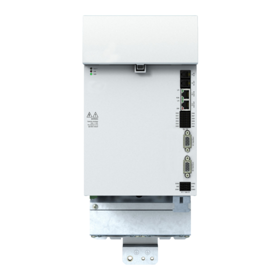
Page 26: Connections, Servoone Cm-A Active Supply Unit
Electrical installation Electrical installation Operation Manual ServoOne CM-L and ServoOne CM-A ID no.: 1800.208B.1-00 Date: 03/2020 4.3.2 Connections, ServoOne CM-A active supply unit Abbreviation Designation Details SO CM-A.00L2 See Section 4.8 and 24 V DC/GND 24 V control supply output via busbars Section 4.9 DC Link +/- DC link supply output via busbars... - Page 27 SO CM-A.00L4 Abbreviation Designation Details 24 V DC/GND 24 V control supply output via busbars See Section 4.9 DC Link +/- DC link supply output via busbars See Section 4.9 + 24 V DC See Section 4.12.1"Specifica- Cross-communication input (XC IN) tion, cross-communication (X3 Cross-communication output (XC OUT) and X4)"...
-
Page 28: Connections, Servoone Cm-D Active Supply Unit (In Preparation)
Electrical installation Electrical installation Operation Manual ServoOne CM-L and ServoOne CM-A ID no.: 1800.208B.1-00 Date: 03/2020 4.3.3 Connections, ServoOne CM-D active supply unit (in Abbreviation Designation Details preparation) 24 V DC/GND 24 V control supply output via busbars See Section 4.9 DC Link +/- DC link supply output via busbars See Section 4.9... -
Page 29: Protective Earth Conductor Connection
Protective earth conductor connection 4.4.2 Connection principle Step Action Comment Connect the PE connections on the ServoOne CM-A active supply unit, the Each device in the axis group must be ServoOne CM-L charging module, the axis controllers earthed! and the controller in a star topology to the PE rail (main earth) in the switch cabinet. -
Page 30: Electrical Isolation Concept
Electrical installation Electrical installation Operation Manual ServoOne CM-L and ServoOne CM-A ID no.: 1800.208B.1-00 Date: 03/2020 Electrical isolation concept Note: Always comply with local and national regulations and conditions. The control terminals are designed as protective extra low voltage (PELV) circuits and must only be operated with such PELV voltages, as per the relevant specification. - Page 31 Abbre- Connections Description Potential viation ϑ LINE IN Mains supply for pre-charging Low voltage Mains +24 V +24 V PELV Protective extra low voltage DC Link+ DC Link+ 24 V PELV Busbars 24 V 24 V switched-mode power supply output PELV Netz/Line DC Link -...
-
Page 32: Ac Mains Connection (Power Supply)
Electrical installation Electrical installation Operation Manual ServoOne CM-L and ServoOne CM-A ID no.: 1800.208B.1-00 Date: 03/2020 AC mains connection (power supply) 4.6.2 Layout, ServoOne CM-A active supply unit LINE FILTER and SYNC (SO CM-A.00L2) 4.6.1 Layout, ServoOne CM-L charging module LINE IN Figure 4.9 Layout, ServoOne CM-A active supply unit LINE FILTER and SYNC (SO CM-A.00L2) -
Page 33: Layout, Servoone Cm-A Active Supply Unit Line Filter And Sync (So Cm-A.00L4)
4.6.3 Layout, ServoOne CM-A active supply unit LINE FILTER 4.6.4 Layout, ServoOne CM-D active supply unit LINE FILTER and SYNC (SO CM-A.00L4) and SYNC (SO CM-D.00L2) *) LINE FILTER Figure 4.10 Layout, ServoOne CM-A active supply unit LINE FILTER and SYNC Figure 4.11 Layout, ServoOne CM-D active supply unit LINE FILTER and SYNC (SO CM-A.00L4) -
Page 34: Power Supply Mains Connection Servoone Cm-L, Servoone Cm-A And Servoone Cm-D
For separate interference suppression on the ServoOne CM system, an optimised mains filter (13) from KEBA can be connected to the connection LINE Filter (L1, L2, L3) on On this topic, see “Figure 4.13 Connection example, mains supply ServoOne CM-A L4 the supply unit. - Page 35 Netz/Line Netz/Line (1) MotionOne CM controller (8) Star topology earthing (1) MotionOne CM controller (8) Star topology earthing (2) ServoOne CM-S switched-mode power supply (9) HF litz wire (2) ServoOne CM-S switched-mode power supply (9) HF litz wire (3) ServoOne CM-L charging module (10) Backing plate (3) ServoOne CM-L charging module (10) Backing plate...
-
Page 36: Servoone Cm-L: Specification Of The Line In Connection
Electrical installation Electrical installation Operation Manual ServoOne CM-L and ServoOne CM-A ID no.: 1800.208B.1-00 Date: 03/2020 4.6.6 ServoOne CM-L: Specification of the LINE IN connection 4.6.7 ServoOne CM-A: specification, LINE FILTER, SYNC and LC (Temp) connections The mains voltage (L1, L2, L3) for power connection is connected to the LINE IN connector. -
Page 37: Servoone Cm-D: Specification, Line Filter, Sync And Lc (Temp) Connections
SO CM-A.00L4.x SO CM-D00L2.x Des. Term. Specification Connection Des. Term. Specification Connection x AC mains connection x 3 x 230...480 V AC x AC mains connection x Connection cross-section: maximum 16 x 3 x 230...480 V AC LINE FILTER x Connection cross-section: maximum 35 mm x Connect cable shield to the shield con- LINE FILTER... -
Page 38: Residual Current Device
Table 4.12 Mains fuses ServoOne CM-L and ServoOne CM-A Before you use this type of system, please contact your sales representative or technical contact at KEBA Industrial Automation Germany GmbH for information on the boundary conditions that need to be met. -
Page 39: 24 V Control Voltage Supply
24 V control voltage supply 4.8.2 Control supply via external 24 V power supply unit The 24 V connection (X2) (see Figure 4.14 and Figure 4.15) on the top of the The 24 V voltage for the supply of the control sections in the ServoOne CM system ServoOne CM-L charging module is used to provide the 24 V voltage from an external BG3+4 can be provided either switched-mode power supply (SMPS) to supply the control sections in the... - Page 40 Electrical installation Electrical installation Operation Manual ServoOne CM-L and ServoOne CM-A ID no.: 1800.208B.1-00 Date: 03/2020 Specification, 24 V DC (X2) Des. Term. Specification Connection 24 V DC Netzteil (Power Supply) +24 V x 24 V DC ± 10 % 24 V DC The sum of the power required via the busbars must not exceed 840 W.
-
Page 41: Busbars For The Supply Voltages
Busbars for the supply voltages Key: (1) Mains fuse for DC link supply (2) Mains fuse for external switched-mode The DC link supply comes from a DC link on the ServoOne CM-A active supply unit power supply ϑ +24 V +24 V and is connected to the lower busbar (DC Link +/-) in the axis group (charging module, (3) Mains contactor (optional) -
Page 42: Busbars, 24 V Control Supply With So Cm-S
24 V DC Netzteil (Power Supply) Note: On the usage of other connection elements (busbars), KEBA Industrial Automation Germany GmbH does provide any guarantee for stable, reliable operation. 4.9.1 Busbars, 24 V control supply with SO CM-S (1) External switched-mode power supply... -
Page 43: Dc Link Supply
4.9.3 DC link supply 4.9.4 Overview of busbars in the group DC-Link + DC-Link - (1) External switched-mode power supply (2) MotionOne CM controller (3) ServoOne CM-L charging module (4) ServoOne CM-A active supply unit (5) ServoOne CM-C capacitance module (6) ServoOne CM axis controller x DC link voltage 565/678 V DC x Depending on mains voltage (400 V/480 V) -
Page 44: 4.10 Connection For Braking Resistor X11
Electrical installation Electrical installation Operation Manual ServoOne CM-L and ServoOne CM-A ID no.: 1800.208B.1-00 Date: 03/2020 4.10 Connection for braking resistor X11 y The connection cross-section for the cable for the braking resistor must correspond at least to the connection cross-section of the supply unit. Otherwise the cables are to be protected by other, suitable measures. - Page 45 Damage to neighbouring assemblies and risk of injury due to hot surfaces Warning! on the external braking resistor! Carelessness may result in serious burns. x Intensive thermal radiation is produced by the braking resistor (>300 °C). x For this reason maintain sufficient clearance to neighbouring assemblies or install the braking resistor outside the switch cabinet.
-
Page 46: Control Connections Servoone Cm-L Charging Module
Electrical installation Electrical installation Operation Manual ServoOne CM-L and ServoOne CM-A ID no.: 1800.208B.1-00 Date: 03/2020 4.11 Control connections ServoOne CM-L charging module Step Action Comment Make a connection between the connection X3 XC OUT on the For this purpose use the cable ServoOne CM-L charging module and X3 XC IN on the next device supplied of type: XCOM. -
Page 47: Specification, Cross-Communication (X3)
Key to the layout, ServoOne CM-L charging module 4.11.2 Specification, connection "State" (X6) Abbrevia- Des. Abbreviation Specification Details Item Designation Details tion RO01NC = normally Relay contact: LED red Supply unit error status (flashing See Section 5.1.1 closed contact RO01NC ≤... -
Page 48: Specification, Connection Of Temperature Sensor (X1)
Electrical installation Electrical installation Operation Manual ServoOne CM-L and ServoOne CM-A ID no.: 1800.208B.1-00 Date: 03/2020 4.12 Control connections 4.11.4 Specification, connection of temperature sensor (X1) ServoOne CM-A active supply unit Des. Abbreviation Specification Details Connection for mains filter (ϑ ) and mains Step Action... - Page 49 Key to the layout, ServoOne CM-A and ServoOne CM-D Item Abbreviation Designation Details LED red Supply unit error status (flashing (ERR) code) See Section 5.1.2. LED green Status mains supply available (Voltage) Cross-communication input XC IN See section “4.12.1 Specification, X3 XC IN ...
-
Page 50: Specification, Cross-Communication (X3 And X4)
Electrical installation Electrical installation Operation Manual ServoOne CM-L and ServoOne CM-A ID no.: 1800.208B.1-00 Date: 03/2020 4.12.1 Specification, cross-communication (X3 and X4) 4.12.2 Specification, EtherCAT® (X5.1 and X5.2) The EtherCAT® field bus interface X5.1 is typically used for the connection of the Des. -
Page 51: Digital Inputs (X6) (Standard Functions)
For a shielded connection up to a length of ≤ 20 m, the following tested cable or an Abbrevi- Des. Specification Electrical isolation equivalent cable must be used: ation Cat. 5e patch cable, S/STP 4x2x0.14 mm2, twisted pair and shielded data DI00 Standard dig. -
Page 52: 4.12.4 Specification, X11 Safe-Di
Electrical installation Electrical installation Operation Manual ServoOne CM-L and ServoOne CM-A ID no.: 1800.208B.1-00 Date: 03/2020 4.12.4 Specification, X11 Safe-DI Note: You will find the specification for the inputs SDIxx and further details on the SD0 function in connection with the bank of DIL switches S-ADR in the ServoOne CM-A document "Model Description SD0"... -
Page 53: 4.15 Commissioning
4.15 Commissioning Note: A maximum of 8 axis controllers (corresponds to maximum 16 axes) can be connected and operated on one supply unit. You will find a description of commissioning in the Operation Manual ServoOne CM Axis Controller (BG3+4) chapter 4. Key to connection example Connection example, supply unit 3 x 400 V Item... - Page 54 Electrical installation Electrical installation Operation Manual ServoOne CM-L and ServoOne CM-A ID no.: 1800.208B.1-00 Date: 03/2020 Note: The supply unit does not protect the upstream components (3, 5, 6, 24) against thermal or electrical hazards. Corresponding protective measures are to be taken.
-
Page 55: Diagnostics
Diagnostics Operating indication: Error indication: Behaviour Voltage (Green) ERR (red) The DC link is in the pre-charging phase, Flashing quickly Status indication LED can take a few seconds. There is an error, the DC link is discon- The DC link is pre-charged and the active nected from the system. -
Page 56: Servoone Cm-A Active Supply Unit
Diagnostics Diagnostics Operation Manual ServoOne CM-L and ServoOne CM-A ID no.: 1800.208B.1-00 Date: 03/2020 5.1.2 ServoOne CM-A active supply unit Status of the active supply unit Supply yellow green Supply LED yellow Status: on = (Reset/Starting) Supply 1) Yellow Supply LED Status: flickering =... -
Page 57: Servoone Cm-D Active Supply Unit
5.1.3 ServoOne CM-D active supply unit Flashing code The Axis 1 LED (yellow) only has a defined function during a software update. AXIS1 State of the axis Axis 1 yellow green Axis 1 short (0.4 long (0.8 s) long (0.8 s) Supply Reset / starting ... - Page 58 Diagnostics Diagnostics Operation Manual ServoOne CM-L and ServoOne CM-A ID no.: 1800.208B.1-00 Date: 03/2020 SUPPLY Status of the active supply unit Supply yellow green Reset / starting or loading firmware update Self-initialisation on device startup (Initialisation) ...
-
Page 59: Appendix
Appendix A.1.1 Technical data, ServoOne CM-L charging module brake chopper Note: Device Unit ServoOne CM-L charging module Until the type test is completed, all technical data are only calculated values Mains voltage V AC and not assured characteristics! Brake chopper power electronics Brake chopper switching threshold V DC Technical data,... -
Page 60: Technical Data, Servoone Cm-A Active Supply Unit
Appendix Appendix Operation Manual ServoOne CM-L and ServoOne CM-A ID no.: 1800.208B.1-00 Date: 03/2020 Technical data, Ambient conditions ServoOne CM-A active supply unit Ambient conditions ServoOne CM-L and ServoOne CM-A Protection Device: IP20 - exception terminals (IP00) Device Unit SO CM-A.00L2 *) SO CM-A.00L4 **) Input, mains side Accident prevention regulations... -
Page 61: Power Reduction At Tunom
Power reduction at T ≥ 40 °C Note: unom The climatic conditions apply to the device. For this reason they must also be met in the switch cabinet. If the multi-axis system is operated outside the specified maximum ambient temperature ), the output power of the axis controllers must be reduced as a function of the unom Mechanical conditions... -
Page 62: Certification
The ServoOne CM-A active supply unit and the ServoOne CM-L charging module thus cooling medium is to be approved by KEBA if it differs from the information conform to the requirements for installation in a machine or plant under the terms of the stated below. -
Page 63: Accessories
Mains filter Accessories Details for this chapter were not yet available at the time of going to press! We have supplemented the ServoOne CM system with comprehensive accessories. Important components are, e.g.: Compliance with the EMC Directive Synchronous servomotors from the product ranges LSH/LST/LSN and LSP Commissioning (i.e. - Page 64 Appendix Appendix Operation Manual ServoOne CM-L and ServoOne CM-A ID no.: 1800.208B.1-00 Date: 03/2020...
- Page 65 Glossary Capacitor charging ................11, 23, 45 CE certification ..................... 62 CE marking ....................62 Charging module ................. 10, 15, 19, 25 Symbole Climatic conditions ..................60 Commissioning ................23, 53, 63 2006/42/EC .................... 12, 62 Connection principle ..................29 2014/30/EU ....................
- Page 66 Glossary Glossary Operation Manual ServoOne CM-L and ServoOne CM-A ID no.: 1800.208B.1-00 Date: 03/2020 Earthing Layout ......................49 Earthing measures ......................25 Layouts ......................25 Earthing measures ..................25 Leakage current ..................29, 30 Electrical installation ................. 15, 23, 25 Liquid cooling ....................
- Page 67 Protective earth conductor connection ........26, 27, 28, 29, 53 STO (Safe Torque OFF) STO ............................. 60 PtP Ethernet connection ..............56, 57, 58 Supply unit ..................10, 15, 19 Switch cabinet ................15, 23, 29, 60 Switched-mode power supply External switched-mode power supply ................
- Page 68 Glossary Glossary Operation Manual ServoOne CM-L and ServoOne CM-A ID no.: 1800.208B.1-00 Date: 03/2020...
- Page 69 Operation Manual ServoOne CM-L and ServoOne CM-A ID no.: 1800.208B.1-00 Date: 03/2020...
- Page 70 Czech Republic • Turkey • USA Copyright © 2020 KEBA All rights reserved. All content of the documentation, in particular the text, photographs and graphics it contains are protected by copyright. The copyright lies, unless otherwise expressly stated, with KEBA Industrial Automation Germany GmbH.
Need help?
Do you have a question about the ServoOne CM Series and is the answer not in the manual?
Questions and answers