
Related Manuals for Siemens RUGGEDCOM RMC41


Summary of Contents for Siemens RUGGEDCOM RMC41
- Page 1 Preface Introduction Installing the Device RUGGEDCOM RMC41 Communication Ports Technical Specifications Certification Installation Guide 07/2018 RC1010-EN-08...
- Page 2 Warranty Siemens warrants this product for a period of five (5) years from the date of purchase, conditional upon the return to factory for maintenance during the warranty term. This product contains no user-serviceable parts. Attempted service by unauthorized personnel shall render all warranties null and void.
-
Page 3: Table Of Contents
RUGGEDCOM RMC41 Installation Guide Table of Contents Table of Contents Preface ......................Alerts ..............................v Training .............................. vi Customer Support ..........................vi Chapter 1 Introduction ..................... 1.1 Feature Highlights ........................1 1.2 Description ........................... 2 1.3 Required Tools and Materials ......................3 1.4 Supported Fiber Optic Cables ...................... - Page 4 RUGGEDCOM RMC41 Table of Contents Installation Guide 4.6 Mechanical Specifications ......................19 4.7 Dimension Drawings ........................19 Chapter 5 Certification ....................5.1 Approvals ........................... 21 5.1.1 CSA ..........................21 5.1.2 European Union (EU) ....................... 22 5.1.3 FCC ..........................22 5.1.4 FDA/CDRH ........................
-
Page 5: Preface
Installation Guide Preface Preface This guide describes the RUGGEDCOM RMC41. It describes the major features of the device, installation, commissioning and important technical specifications. It is intended for use by network technical support personnel who are responsible for the installation, commissioning and maintenance of the device. -
Page 6: Training
Siemens Sales representative. Customer Support Customer support is available 24 hours, 7 days a week for all Siemens customers. For technical support or general information, contact Siemens Customer Support through any of the following methods: Online Visit http://www.siemens.com/automation/support-request... -
Page 7: Introduction
An operating temperature range of -40 to 85 °C (-40 to 185 °F) without the use of internal cooling fans allows it to be placed in almost any location. The RUGGEDCOM RMC41 is compliant with EMI and environmental standards for utility substations, industrial manufacturing, process and control and intelligent transportation systems applications. -
Page 8: Description
Section 1.2 Description The RUGGEDCOM RMC41 features various ports, controls and indicator LEDs on the display panel for connecting, configuring and troubleshooting the device. The display panel can be located on the rear, front or top of the device, depending on the mounting configuration. -
Page 9: Required Tools And Materials
RUGGEDCOM RMC41, refer to Chapter 3, Communication Ports. Section 1.3 Required Tools and Materials The following tools and materials are required to install the RUGGEDCOM RMC41: Tools/Materials Purpose AC or DC power cord (16 AWG) For connecting power to the device. CAT-5 Ethernet cables For connecting the device to the network. -
Page 10: Decomissioning And Disposal
Chapter 1 RUGGEDCOM RMC41 Introduction Installation Guide Section 1.5 Decomissioning and Disposal Proper decomissioning and disposal of this device is important to prevent malicious users from obtaining proprietary information and to protect the environment. Decommissioning This device may include sensitive, proprietary data. Before taking the device out of service, either permanently or for maintenance by a third-party, make sure it has been fully decommissioned. -
Page 11: Installing The Device
This product contains no user-serviceable parts. Attempted service by unauthorized personnel shall render all warranties null and void. Changes or modifications not expressly approved by Siemens Canada Ltd could invalidate specifications, test results, and agency approvals, and void the user's authority to operate the equipment. -
Page 12: Unpacking The Device
Section 2.3 Mounting the Device The RUGGEDCOM RMC41 is designed for maximum mounting and display flexibility. It can be equipped with connectors that allow it to be installed in a 35 mm (1.4 in) DIN rail or directly on a panel. -
Page 13: Mounting The Device On A Din Rail
RUGGEDCOM RMC41 Chapter 2 Installation Guide Installing the Device Section 2.3.1 Mounting the Device on a DIN Rail For DIN rail installations, the RMC41 can be equipped with a DIN rail bracket pre-installed on the back of the chassis. The bracket allows the device to be slid onto a standard 35 mm (1.4 in) DIN rail. -
Page 14: Connecting Power
Install the screw previously removed from the bottom of the panel adapter. Section 2.4 Connecting Power The RUGGEDCOM RMC41 supports a single integrated high AC/DC or low DC power supply NOTE • For 110/230 VAC rated equipment, an appropriately rated AC circuit breaker must be installed. -
Page 15: Connecting Ac Power
Installing the Device IMPORTANT! Siemens requires the use of external surge protection in VDSL applications where the line may be subject to surges greater than that for which the device is rated. Use the following specifications as a guide for VDSL external surge protection: •... -
Page 16: Connecting Dc Power
Chapter 2 RUGGEDCOM RMC41 Installing the Device Installation Guide Figure 4: Terminal Block Wiring 1. Positive/Live (+/L) Terminal 2. Negative/Neutral (-/N) Terminal 3. Surge Ground Terminal 4. Braided Ground Cable Connect the negative wire from the power source to the negative/neutral (-/N) terminal on the terminal block. - Page 17 RUGGEDCOM RMC41 Chapter 2 Installation Guide Installing the Device Figure 5: Terminal Block Wiring 1. Positive/Live (+/L) Terminal 2. Negative/Neutral (-/N) Terminal 3. Surge Ground Terminal 4. Braided Ground Cable Connect the negative wire from the power source to the negative/neutral (-/N) terminal on the terminal block.
- Page 18 Chapter 2 RUGGEDCOM RMC41 Installing the Device Installation Guide Connecting DC Power...
-
Page 19: Communication Ports
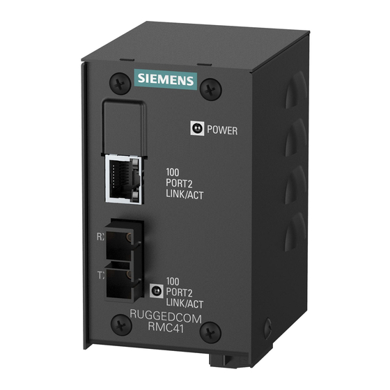
RUGGEDCOM RMC41 Chapter 3 Installation Guide Communication Ports Communication Ports The RUGGEDCOM RMC41 can be equipped with various types of communication ports to enhance its abilities and performance. Figure 6: Port Assignment 1. Port 1 2. Port 2 Port Type Copper Ethernet Port Fiber Optic Ethernet Port CONTENTS •... - Page 20 Chapter 3 RUGGEDCOM RMC41 Communication Ports Installation Guide WARNING! Electric shock hazard – risk of serious personal injury and/or equipment interference. If shielded cables are used, make sure the shielded cables do not form a ground loop via the shield wire and the RJ45 receptacles at either end.
-
Page 21: Fiber Optic Ethernet Ports
RUGGEDCOM RMC41 Chapter 3 Installation Guide Communication Ports Section 3.2 Fiber Optic Ethernet Ports Fiber optic Ethernet ports are available with either SC (Standard or Subscriber Connector) or ST (Straight Tip) connectors. Make sure the Transmit (Tx) and Receive (Rx) connections of each port are properly connected and matched to establish a proper link. - Page 22 Chapter 3 RUGGEDCOM RMC41 Communication Ports Installation Guide Fiber Optic Ethernet Ports...
-
Page 23: Technical Specifications
RUGGEDCOM RMC41 Chapter 4 Installation Guide Technical Specifications Technical Specifications This section provides important technical specifications related to the device and available modules. CONTENTS • Section 4.1, “Power Supply Specifications” • Section 4.2, “Copper Ethernet Port Specifications” • Section 4.3, “Fiber Optic Ethernet Port Specifications”... -
Page 24: Fiber Optic Ethernet Port Specifications
To convert from peak to average, subtract 3 dBm. • Maximum segment length is greatly dependent on factors such as fiber quality, and the number of patches and splices. Consult a Siemens Sales associate when determining maximum segment distances. Wavelength (nm) -
Page 25: Operating Environment
RUGGEDCOM RMC41 Chapter 4 Installation Guide Technical Specifications Parameter 10Base-FL 100Base-FX Notes IEEE 802.3x Full Duplex, Flow Control Section 4.5 Operating Environment Parameter Range Comments Ambient Operating Temperature -40 to 85 °C Measured from a 30 cm (12 in) radius surrounding the center of the (-40 to 185 °F) - Page 26 Chapter 4 RUGGEDCOM RMC41 Technical Specifications Installation Guide 90.4 80.1 73.7 62.2 58.4 70.7 Figure 10: Overall Dimensions 67.3 62.2 92.5 58.4 82.2 35.6 11.4 Figure 11: Panel Mount Dimensions Dimension Drawings...
-
Page 27: Certification
RUGGEDCOM RMC41 Chapter 5 Installation Guide Certification Certification The RUGGEDCOM RMC41 device has been thoroughly tested to guarantee its conformance with recognized standards and has received approval from recognized regulatory agencies. CONTENTS • Section 5.1, “Approvals” • Section 5.2, “EMC and Environmental Type Tests”... -
Page 28: European Union (Eu)
Information Technology Equipment – Radio disturbance characteristics – Limits and methods of measurement The device is marked with a CE marking and can be used throughout the European community. A copy of the CE Declaration of Conformity is available from Siemens Canada Ltd. For contact information, refer to “Contacting Siemens”. -
Page 29: Rohs
• CAN ICES-3 (A)/NMB-3 (A) Section 5.1.6 RoHS This device is declared by Siemens Canada Ltd to meet the requirements of the following RoHS (Restriction of Hazardous Substances) directives for the restricted use of certain hazardous substances in electrical and electronic equipment: •... - Page 30 AC Power Ports 5 kV Siemens specified severity level. IEEE 1613 EMC Immunity Type Tests NOTE The RUGGEDCOM RMC41 meets Class 2 requirements for an all-fiber configuration and Class 1 requirements for copper ports. Description Test Levels Enclosure Contact ± 8 kV Enclosure Air ±...
- Page 31 RUGGEDCOM RMC41 Chapter 5 Installation Guide Certification Description Test Levels DC Power Ports 2.5 kV common, 1 kV differential mode @ 1MHz AC Power Ports 2.5 kV common, 1 kV differential mode @ 1MHz HV Impulse Signal Ports 5 kV (Failsafe Relay)
- Page 32 Chapter 5 RUGGEDCOM RMC41 Certification Installation Guide EMC and Environmental Type Tests...
Need help?
Do you have a question about the RUGGEDCOM RMC41 and is the answer not in the manual?
Questions and answers