
Related Manuals for sauermann E INSTRUMENTS E6000


Summary of Contents for sauermann E INSTRUMENTS E6000
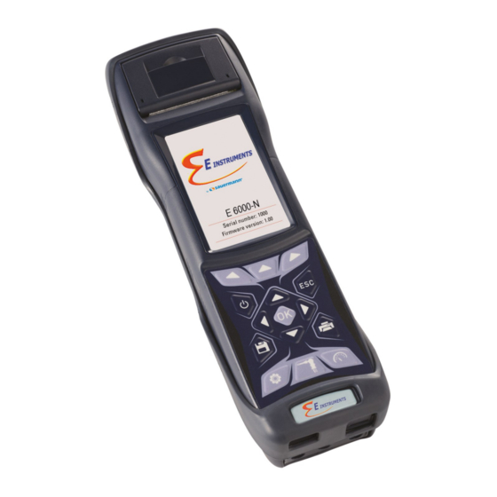
- Page 1 E6000 Combustion Analyzer OPERATING & MAINTENANCE MANUAL Respect your environment: think before printing the full manual on paper...
-
Page 3: Table Of Contents
TABLE OF CONTENTS IMPORTANT INFORMATION 1.1 Information about this manual 1.2 Safety warnings SAFETY 2.1 Intended use of the product 2.2 Improper use of the product WORKING PRINCIPLE 3.1 General overview of the Analyzer DESCRIPTION OF THE PRODUCT Working principle Measurement cells CO dilution Fuel types... - Page 4 TABLE OF CONTENTS 8.5.8 Draft measurement pressure gauge compliant with UNI 10845 standard. 8.5.9 Pressure Test Kit 8.5.10 Burner pressure verification probe 8.5.11 Connection to PC 8.5.12 Connection to battery charger POWER ON - OFF Starting the device 10.0 CONFIGURATION 10.1 Configuration Menu 11.0 MEMORY...
- Page 5 ANNEX D - Optional measures list ANNEX E - Declaration of Conformity E INSTRUMENTS by SAUERMANN - ALL RIGHTS RESERVED - Total or partial reproduction of this document by any means (including photocopying or storage on any electronic medium) and transmittal of same to third parties in any manner, even electronically, is strictly prohibited unless explicitly authorized in writing by E INSTRUMENTS by SAUERMANN.
- Page 6 K600000000EJ 032438 220519...
-
Page 7: Important Information
07/08/14 10:00 Service Information E Instruments by Sauermann 850 Town Center Drive Information on LCD Langhorne, PA 19047 USA Phone: 1-215-750-1212 www.e-inst.com sales.instruments @sauermanngroup.com Dispose of the battery pack at the end of its working life only at the dedicated collecting bin. -
Page 8: Safety
SAFETY 2.1 Intended purpose This chapter describes the areas of application for which the E6000 is intended. Using the E6000 in other application areas is at the risk of the operator and the manufacturer assumes no responsibility and liability for loss, damage or costs which could be a result. It is mandatory to read and pay attention to the operating/maintenance manual. -
Page 9: Working Principle
WORKING PRINCIPLE 3.1 General overview of the Analyzer E6000 is a portable analyzer for flue gas and emissions. The instrument is equipped with: Pneumatic circuit which can accommodate up to 6 sensors in the FLEX-sensors series. Intuitive user interface: the instrument can be used without the support of the user manual. ... - Page 10 Maintenance: - Sensors can be replaced by the user without having to ship the instrument to the service center, because the spare sensors delivered are pre-calibrated. - The instrument requires annual calibration, as required by the standard UNI 10389-1, to be carried out at any authorized service center.
-
Page 11: Description Of The Product
4.0 DESCRIPTION OF THE PRODUCT 4.1 Working principle The gas sample is taken in through the gas probe, by a diaphragm suction pump inside the instrument. The measuring probe has a sliding positioning cone that allows the probe to be inserted in holes with a diameter of 11 mm (0.43”) to 16 mm (0.65”) and to adjust the immersion depth. -
Page 12: Fuel Types
of very high concentration of CO. The dilution system also allows to extend the measurement range of the CO sensor as follows: - up to 100,000 ppm for a CO sensor with 8000 ppm full scale - up to 250,000 ppm for a CO sensor with 20,000 ppm full scale In this way in addition to better manage the wearing of the sensor, it is also possible to continue sampling, without any work interruption. -
Page 13: Bluetooth® Connection
4.11 Bluetooth® connection The E6000 analyzer is internally equipped with a Bluetooth® module, which allows the communication with the following remote devices: - Remote Bluetooth® printer - Smartphone or tablet with installed the OS Google Android v.4.1 (Jelly Bean) or later and the proper APP ‘E-Inst. -
Page 14: Description Of Components
5.0 DESCRIPTION OF COMPONENTS LEGEND: keypad Adhesive polyester keypad with preformed keys featuring main control functions. KEYS FUNCTION KEYS FUNCTION Activates the context Turns the device On / keys shown on the display Access to the Memory Exits the current screen menu Access to the Printing Select and/or Modify... - Page 15 Display TFT 272 x 480 pixel backlit color display with 21 characters available and 8 lines. Allows the user to view the measured parameters in the most comfortable format; a Zoom function displays the measured values in magnified form. CAUTION: If the instrument is exposed to extremely high or extremely low temperatures, the quality of the display may be temporarily impaired.
- Page 16 Used to connect the Tc-K plug of the combustion air temperature probe. 'T1' Connector Used to connect the Tc-K male connector of the gas temperature probe. Gas outlet 'AUX' Connector Input for optional external probes. 'P-' Pneumatic connector Pressure negative input (P-): used for measuring draft according to the standard UNI10845; it connects to the second hose (with the larger pneumatic connector) of the sample probe for simultaneous measurement of draft and combustion analysis.
-
Page 17: Main Configurations
MAIN CONFIGURATIONS E6000- E6000- E6000-5DS E6000-5DC E6000-5SC E6000-5SH 6DSH 6DSC O2 SENSOR CO+H2 SENSOR CO+H2 SENSOR low range CO SENSOR CO SENSOR 0 .. 100.000 ppm CO SENSOR 0 .. 20000 ppm ... -
Page 18: Technical Specifications
TECHNICAL SPECIFICATIONS 7.1 Technical features Power supply: Li-Ion battery pack with internal protection circuit, rechargeable. Battery charger: External 5Vdc 2A battery charger with female A-type USB connector + connection to the device with the same serial communication cable supplied. Charging time: 5 hours to charge from 0% to 90% (6 hours for 100%). - Page 19 Smoke: Using an external hand pump; it is possible to enter and print the smoke index. Leak test: Gas pipes tested for leaks with separate printout of the result, by means of the attachment AACKT02, according to UNI 7129 (new systems) and UNI 11137: 2012 (existing systems), with automatic calculation of pipe volume.
-
Page 20: Measurement And Accuracy Ranges
7.2 Measurement and Accuracy Ranges MEASUREMENT SENSOR RANGE RESOLUTION ACCURACY Electrochemical sensor 0 .. 25.0% vol 0.1% vol ±0,2% vol ±10 ppm 0 .. 200 ppm Electrochemical sensor 0 .. 8000 ppm 1 ppm ±5% measured value 201 .. 2000 ppm with H compensation ±10% measured value... -
Page 21: Using The Flue Gas Analyzer
8.0 USING THE FLUE GAS ANALYZER Preliminary operations Remove the instrument from its packing and check it for damage. Make sure that the content corresponds to the items ordered. If signs of tampering or damage are noticed, notify the E Instruments service center or distributor immediately and keep the original packing. -
Page 22: Analyzer Power Supply
8.3 Analyzer power supply The instrument contains a high-capacity Li-Ion rechargeable battery. The battery feeds the instrument, built-in printer and any other probes or remote devices that may be connected. The instrument runs for approximately 18 hours if the printer is not used. Should the battery be too low to effect the necessary measurements, the instrument can be hooked up to the mains via the power pack provided, allowing operations (and analysis) to proceed. -
Page 23: Connection Diagram
8.5 Connection diagram CONDENSATE TRAP WITH IONIZATION PARTICULATE CURRENT FILTER MEASUREMENT (AACTA03A) PROBE (AACSO01) PRESSURE COMBUSTION MICRO- AIR PROBE MANOMETER GAS SAMPLING PROBE (AACKP01) (AA SA08) (AACDP02) (AASF--) K600000000EJ 032438 220519... - Page 24 POWER SUPPLY / BATTERY CHARGER (AAAL05) GAS SAMPLING PROBE FOR INDUSTRIAL ENGINES (AASX02) K600000000EJ 032438 220519...
-
Page 25: Gas Sampling Probe
8.5.1 Gas sampling probe General description The gas sampling probe is made of a stainless steel tube with a plastic hand grip and includes an internal K-type thermocouple (Ni-NiCr) for measuring the gas temperature of the gas. The thermocouple is located in the probe tip. -
Page 26: Condensate Trap And Fine Dust Filter
8.5.3 Connecting the gas sampling probe (Standard / average CO) and water-trap assembly As shown in section 8.5 the gas sampling probe must be connected to the device as follows: The polarized male connector of the thermocouple must be connected to the lower part of the device in the T1 ... -
Page 27: Combustion Air Temperature Sensor
8.5.6 Tc-K temperature measurement probe Using the same input as for the Tc-K thermocouple ‘T1’ (i.e. the one used for gas temperature), it is possible to measure the supply and return water temperature. If this temperature is taken on the pipe itself, it is suggested to use contact probes with diameter matching as close as possible the pipe diameter. -
Page 28: Connection To Battery Charger
8.5.12 Connection to battery charger Supplied with the device is a feeder with output 5VdC, 2A to charge the internal batteries. In section 5 you can see the socket for the connection of the battery charger to the device. Once it has started charging, the display turns on and the state of charge of the battery is displayed. -
Page 29: Power On - Off
POWER ON - OFF Starting the device Press and hold for a few seconds. 04/03/16 04/03/16 04/03/16 10:00 10:00 10:00 Combustion analysis Combustion analysis Combustion analysis WARNING λ,n λ,n λ,n 1.25 1.25 Do not insert the gas probe in the chiminey T flue T flue 190.1... - Page 30 FUNCTION Activate the context keys shown on the display. Goes through the measurements available. Activates the context key located in the left side of the display. Returns to the previous screen. CONTEXT KEY FUNCTION Repeats autozero (is shown in the case of an error). The device will suspend autozero and display the screen "Combustion Analysis";...
-
Page 31: Configuration
10.0 CONFIGURATION 10.1 Configuration menu 15/01/14 FUNCTION 10:00 Activate the context keys shown on the Configuration display. Returns to the previous screen. Analysis Instrument CONTEXT KEY FUNCTION Operator Alarms ◄ Selects the available parameters. Information Diagnostic Enters in the selected parameter setting. Language Restore ►... - Page 32 10.2 Configuration→Analysis → 15/01/14 FUNCTION 10:00 Activate the context keys shown on the Configuration display. Analysis Returns to the previous screen. Fuel Condensation CONTEXT KEY FUNCTION reference /NO ratio ◄ Selects the available parameters. Measure units Autozero Enters in the selected parameter setting. Measures list Air temp.
- Page 33 10.2.1 Configuration→Analysis→Fuel → 07/08/14 07/08/14 10:00 10:00 Configuration Configuration Fuel Fuel Natural gas Bagasse #2 Oil L.P.G. #4 Oil Butane #6 Oil Propane Diesel Wood/Pellets 8% Coal Bio-Fuel 5% FUNCTION Activate the context keys shown on the display. The arrows select each line displayed. Confirms the choice of fuel to be used during the analysis.
- Page 34 10.2.2 Configuration→Analysis→Condensation → 15/01/14 10:00 Configuration Condensation Altitude Altitude above sea level R.H. air Relative humidity of air FUNCTION Activate the context keys shown on the display. The arrows select each line displayed (the selected line is red). In edit mode, it scrolls through the suggested values. Enters the modify mode for the selected parameter, then confirms the modification.
- Page 35 10.2.3 Configuration→Analysis→Reference O → 15/01/14 10:00 Configuration reference Percentage of Oxygen in CO measurement Percentage of Oxygen in NO measurement Percentage of Oxygen in SO measurement FUNCTION Activate the context keys shown on the display. Keys '▲' and '▼' select any line shown on the display (the selected line is displayed in red).
- Page 36 10.2.4 Configuration→Analysis→NO /NO ratio → 15/01/14 10:00 Configuration /NO ratio 1.05 FUNCTION Activate the context keys shown on the display. When in modify mode, sets the desired value. Enters edit mode of the selected element and then confirms the change. When pressed in modify mode cancels the selection made, otherwise returns to the previous screen.
- Page 37 10.2.5 Configuration→Analysis→Measurement units → 15/01/14 10:00 Configuration Measure units Measurement unit can be set as: ppm - mg/m - mg/kWh - g/GJ - g/m - g/kWh - % - ng/J Measurement unit can be set as: ppm - mg/m - mg/kWh - g/GJ - g/m - g/kWh - % - ng/J Measurement unit can be set as: ppm - mg/m - mg/kWh - g/GJ - g/m...
- Page 38 10.2.6 Configuration→Analysis→Autozero → 15/01/14 10:00 Configuration Autozero Autozero Duration of autozero, expressed in seconds. Purging Duration of the cleaning cycle, expressed in seconds. FUNCTION Activate the context keys shown on the display. When in modify mode, sets the desired value. Enters edit mode of the selected element and then confirms the change.
- Page 39 10.2.7 Configuration→Analysis→Measures list → 15/01/14 10:00 Configuration Measures list λ,n T flue T air ΔT Qs (PCI) FURTHER DETAILS ηs (PCI) ANNEX D » FUNCTION Activate the context keys shown on the display. Select each line displayed (the line selected is red). In edit mode, it sets the desired value.
- Page 40 Example: → 1. Add a measurement to the list - example 15/01/14 15/01/14 15/01/14 15/01/14 10:00 10:00 10:00 10:00 Configuration Configuration Configuration Configuration Measures list Measures list Measures list Measures list λ,n λ,n ▲ T flue T flue λ,n λ,n T air T air T flue...
- Page 41 10.2.8 Configuration→Analysis→Air temperature → 15/01/14 10:00 Configuration Air temperature Probe T 25.0 °C Air T ----- °C FUNCTION Activate the context keys shown on the display. When in modify mode, sets the desired value. Activates the context key located in the left side of the display. Returns to the previous screen without saving the changes made.
- Page 42 10.3 Configuration→Instrument → 04/03/16 FUNCTION 10:00 Activate the context keys shown on the Configuration Instru- ment display. Returns to the previous screen. Bluetooth Time/Date Brightness Buzzer CONTEXT KEY FUNCTION ◄ Selects the available parameters. Pump CO dilution Enters in the selected parameter setting. Micromanometer ►...
- Page 43 10.3.1 Configuration→Instrument→Bluetooth → 15/01/14 10:00 Bluetooth Bluetooth enabling / disabling Status Instrument name E6000 - 0001 MAC address detected 00026BB5500 FUNCTION Activate the context keys shown on the display. Also activates the context key shown on the display. Returns to the previous screen. CONTEXT KEY FUNCTION Turns on Bluetooth communication.
- Page 44 10.3.2 Configuration→Instrument→Time/Date → 15/01/14 10:00 Configuration Time/Date Time, in the chosen format Time 14:00 Date, in the chosen format Date 15/01/14 Date format: EU (Europe) or USA (America) Mode Mode Time format: 24h or 12h FUNCTION Activate the context keys shown on the display. When in modify mode, sets the desired value.
- Page 45 10.3.3 Configuration→Instrument→Brightness → 15/01/14 10:00 Configuration Brightness FUNCTION Activate the context keys shown on the display. Increases or decreases the brightness of the display. Confirms the modification. When pressed in modify mode cancels the selection made, otherwise returns to the previous screen. CONTEXT KEY FUNCTION ◄...
- Page 46 10.3.4 Configuration→Instrument→Buzzer → Available settings : the buzzer is enabled (key tones and signalling of faults/alarms are enabled). limited: the buzzer is enabled in a limited mode (key tones are disabled, while signalling of faults/alarms is enabled). off: the buzzer is disabled. FUNCTION Activate the context keys shown on the display.
- Page 47 10.3.5 Configuration→Instrument→Pump → 15/01/14 10:00 Configuration Pump Pump Flow Displays the flow of the pump, expressed in litres per minute. l/min FUNCTION Activate the context keys shown on the display. When in modify mode, sets the desired value. Enters edit mode of the selected element and then confirms the change. When pressed in modify mode cancels the selection made, otherwise returns to the previous screen.
- Page 48 10.3.6 Configuration→Instrument→CO dilution → 15/01/14 10:00 Configuration CO dilution Available settings: auto, on or off Mode auto Limit Threshold that activates the dilution pump (available only if the "Mode" parameter is set to 4000 "auto"). FUNCTION Activate the context keys shown on the display. Select each line displayed (the line selected is red).
- Page 49 10.3.7 Configuration→Instrument→Micromanometer → 15/01/14 10:00 Configuration Micromanometer Sets the input used for the test: P+ or P- Inlet FUNCTION Activate the context keys shown on the display. In edit mode, it sets the desired input. Enters edit mode of the selected element and then confirms the change. When pressed in modify mode cancels the selection made, otherwise returns to the previous screen.
- Page 50 10.4 Configuration→Operator → 15/01/14 10:00 Configuration Operator Operator 1 Operator 2 Operator 3 Operator 4 Operator 5 Operator 6 Operator 7 Operator 8 FUNCTION Activate the context keys shown on the display. In "edit text": Moves the cursor on the box corresponding to the letter or number required to form the word.
- Page 51 Example: → 1. Edit text 15/01/14 15/01/14 15/01/14 10:00 10:00 10:00 Configuration Edit text Edit text Operator Operator 1 Operator 2 Operator 3 Operator 1_ Operator _ Operator 4 Operator 5 Operator 6 Operator 7 Operator 8 15/01/14 15/01/14 15/01/14 10:00 10:00...
- Page 52 10.5 Configuration→Alarm → 15/01/14 10:00 Configuration Alarms Number of the alarm set Number Monitored parameter: O - CO - NO - NO - P diff - Plow - P ext - T1 - T2 Measure Type of alarm set: maximum - minimum - off Mode maximum Threshold setting for the alarm: ±999999.999...
- Page 53 10.6 Configuration→Information → 04/03/16 FUNCTION 10:00 Activate the context keys shown on the Information display. Returns to the previous screen. Battery Sensors CONTEXT KEY FUNCTION InfoService Reminder ◄ Selects the available parameters. ID number Probes Enters in the selected parameter setting. ►...
- Page 54 10.6.1 Configuration→Information→Battery → 15/01/14 10:00 Information Battery 94 % FUNCTION Activate the context keys shown on the display. Returns to the previous screen. CONTEXT KEY FUNCTION Returns to the previous screen. K600000000EJ 032438 220519...
- Page 55 10.6.2 Configuration→Information→Sensor → 04/03/16 04/03/16 10:00 10:00 Information Diagnostic Sensors Sensors S1: O S1: O S2: CO S2: CO S3: NO S3: NO For further information, see section 10.7.1. S4: NO S4: NO S5: SO S5: SO S6: H S6: H FUNCTION Activate the context keys shown on the display.
- Page 56 10.6.3 Configuration→Information→InfoService → 15/01/14 10:00 FUNCTION Information Service Activate the context keys shown on the display. E Instruments By Sauermann Returns to the previous screen. Tel: (215)750-1212 sales.instruments@ sauermanngroup.com www.e-inst.com CONTEXT KEY FUNCTION Returns to the previous screen. K600000000EJ 032438 220519...
- Page 57 10.6.4 Configuration→Information→Reminder → 15/01/14 10:00 Password Reminder 0 0 0 0 FUNCTION Activate the context keys shown on the display. Sets the password. The password is: 1111. Returns to the previous screen. CONTEXT KEY FUNCTION Confirm password and enter the menu “Reminder”. Returns to the previous screen.
- Page 58 10.6.5 Configuration→Information→Probe → 15/01/14 10:00 FUNCTION Information Probes Activate the context keys shown on the display. Micromanometer int. 1039 External probe ---- Returns to the previous screen. CONTEXT KEY FUNCTION Returns to the previous screen. K600000000EJ 032438 220519...
- Page 59 10.7 Configuration→Diagnostic → 15/01/14 FUNCTION 10:00 Activate the context keys shown on the Diagnostic display. Returns to the previous screen. Sensors Gas probe Hardware Pump CONTEXT KEY FUNCTION ◄ Selects the available parameters. On site cal. Enters in the selected parameter setting. ►...
- Page 60 10.7.1 Configuration→Diagnostic→Sensors → 15/01/14 10:00 Diagnostic Sensors S1: O S2: CO S3: NO S4: NO FUNCTION Activate the context keys shown on the display. Selects the fuel. Activates the context keys located in the left side of the display. Returns to the previous screen. CONTEXT KEY FUNCTION Displays the details of the selected sensor (see example below).
- Page 61 10.7.2 Configuration→Diagnostic→Pump → 15/01/14 10:00 Diagnostic Pump Pump Flow l/min FUNCTION Activate the context keys shown on the display. In edit mode, cycling between on and off. Enters edit mode of the selected element and then confirms the change. Returns to the previous screen. CONTEXT KEY FUNCTION Enters edit mode: it is possible to turn the gas suction pump on and off.
- Page 62 10.7.3 Configuration→Diagnostic→On site cal. → 15/01/14 10:00 Password On site calibration 0 0 0 0 FUNCTION Activate the context keys shown on the display. Sets the password. Selects line; the selected line is displayed in red. In modification sets the value or the desired mode. Activates the context key located in the left side of the display.
- Page 63 Calibration procedure → In order to perform the calibration, the following tools are needed: - Known concentration gas cylinder suitable for the sensor, complete with a pressure regulator WARNING! For the oxygen sensor on site calibration, the zero value calibration must be carried out with nitrogen or any other gas mixture which DOES NOT contain oxygen.
- Page 64 → 3. Once in the ‘On site calibration’ menu, is shown the list of the installed sensors for which the recalibration is available. In the recalibration screen all information related to the last performed calibration is shown, as well as the relevant values. Calibrate: saves new calibration 15/01/14...
- Page 65 CALIBRATION EXAMPLE FOR THE OXYGEN CELL (O → → The calibration will be possible only when the status is set to ‘----' (cells which never had an on-site calibration) or 'inactive'. 15/01/14 15/01/14 15/01/14 10:00 10:00 10:00 On site calibration On site calibration On site calibration Sensor O...
- Page 66 → When the stabilization time is over, select the 'Calibration' row and activate the function ' ' to store the new calibration. Messages in the 'Status' line: 15/01/14 15/01/14 saving: instrument saving 10:00 10:00 performed calibration error: sensor been On site calibration On site calibration Sensor O...
- Page 67 CALIBRATION EXAMPLE FOR TOXIC GAS CELL (CO EXAMPLE). → The calibration will be possible only when the status is set to ‘----' (cells which never had an on-site calibration) or 'inactive'. 15/01/14 15/01/14 15/01/14 10:00 10:00 10:00 On site calibration On site calibration On site calibration Sensor CO...
- Page 68 → When the stabilization time is over, select the 'Calibration' row and activate the function ' ' to store the new calibration. Messages in the 'Status' line: 15/01/14 15/01/14 10:00 10:00 saving: instrument saving performed calibration On site calibration On site calibration error: sensor...
- Page 69 10.7.4 Configuration→Diagnostic→Gas probe → 15/01/14 10:00 Diagnostic Connect the flue gas sampling probe and filter unit assembly to the Gas probe instrument; Fully insert the black rubber cap on the gas probe tip, as shown in Close the flue gas probe the following picture: Press OK to start Black rubber cap...
- Page 70 10.7.5 Configuration→Diagnostic→Hardware → 15/01/14 10:00 Diagnostic Hardware State of memory. Memories State of calibration. Calibration Version of CPU board HW Cpu version Version of motherboard HW MB version FUNCTION Activate the context keys shown on the display. Returns to the previous screen. CONTEXT KEY FUNCTION Returns to the previous screen.
- Page 71 10.8 Configuration→Language 15/01/14 15/01/14 15/01/14 10:00 10:00 10:00 Configurazione Configuration Configuration Lingua Language Language Italiano Italiano Brasileiro English English Galego Français Français Català Espaňol Espaňol Cestina Deutsch Deutsch Polsky Русский Русский Dutch Romana Slovenskému FUNCTION Activate the context keys shown on the display. Scrolls through the available languages.
- Page 72 10.9 Configuration→Restore 15/01/14 15/01/14 10:00 10:00 Configuration Configuration Restore Restore WARNING Clear memory data and Confirm restoring? restore factory setting? F1: restore F2: cancel di fabbrica? FUNCTION Activate the context keys shown on the display. Starts the factory data reset phase. Exits the current screen without resetting.
-
Page 73: Memory
11.0 MEMORY 11.1 Memory Menu 15/01/14 FUNCTION 10:00 Activate the context keys shown on the Memory display. Returns to the previous screen. Save Average CONTEXT KEY FUNCTION Select Data logger ◄ Selects the available parameters. Delete Usage % Enters in the selected parameter setting. ►... - Page 74 Warning: in automatic mode, the measurements of smoke, draft and ambient CO must be taken before starting the combustion analysis. Manual analysis mode If the user chooses the manual mode, he will perform the combustion analysis manually; in this case, the settings regarding printing and duration of the automatic analysis will not be considered.
-
Page 75: Memory Organization
11.1.1 Memory Organization K600000000EJ 032438 220519... - Page 76 11.2 Memory Menu→Save 15/01/14 15/01/14 10:00 10:00 Memory Memory Save Save Manual analysis mode Automatic analysis mode Mode Mode manual UNI 10389 Number of selected memory Number of selected memory Memory Memory Number of samples to take Number of performed analyses Analysis Samples Interval...
- Page 77 Example 1: Saving the combustion analysis in manual mode 15/01/14 15/01/14 15/01/14 10:00 10:00 10:00 Memory Memory Memory Save Save Save Mode Mode manual manual Mode manual Memory Memory Memory Analysis Analysis Analysis Example 2: Saving the combustion analysis in automatic mode (example UNI 10389) 15/01/14 15/01/14 15/01/14...
- Page 78 11.3 Memory Menu→Average 15/01/14 10:00 Memory Average analysis λ,n 1.25 T flue 190.1 °C T air 15.4 °C ΔT 74.7 °C ηs 91.4 FUNCTION Activate the context keys shown on the display. Scrolls through the values of the average analysis. Activates the context key located in the left side of the display.
- Page 79 11.4 Memory Menu→Select 07/08/14 15/01/14 10:00 10:00 Memory Memory Delete single Select Memory number Boiler model Memory Boiler xxxx Customer Customer Address Customer address E Instruments Customer address Address 850 Town Center Dr Langhorme, PA 19047 Phone Telephone number Telephone number Phone 215-750-1212 Boiler model...
- Page 80 11.4.1 Memory Recall 07/08/14 15/01/14 10:00 10:00 Memory Memory Delete single Recall Memory Measure conditions Customer Single analysis E Instruments Address 850 Town Center Dr Average analysis Langhorme, PA 19047 Phone 215-750-1212 Boiler xxxx Date 07/08/14 FUNCTION Activate the context keys shown on the display. Selects line;...
- Page 81 2. Details of Single analysis 15/01/14 15/01/14 10:00 10:00 Memory Memory Single analysis Average analysis 15/01/14 15:10:30 15/01/14 15:15:00 λ,n 15/01/14 15:20:30 1.25 T flue 15/01/14 15:25:00 190.1 °C T air 15/01/14 15:30:35 15.4 °C ΔT 74.7 °C ηs 91.4 ▲...
- Page 82 3. Average interval details 15/01/14 15/01/14 10:00 10:00 Memory Memory Defines the starting sample to define the analysis Average Average analysis average. Defines the end sample to define the analysis λ,n average. 1.25 T flue 190.1 °C T air 15.4 °C ΔT 74.7...
- Page 83 11.5 Memory Menu→Data logger 15/01/14 10:00 Memory Data logger The selectable analysis modes are: manual - UNI 10389 - BImSchV - data logger Mode UNI 10389 Samples Number of samples to make (parameter not visible in manual analysis mode). Interval Period of acquisition of each sample (parameter not visible in manual analysis mode).
- Page 84 11.6 Memory→Delete 15/01/14 FUNCTION 10:00 Activate the context keys shown on the Memory display. Delete Returns to the previous screen. Single CONTEXT KEY FUNCTION ◄ Selects the available parameters. Enters in the selected parameter setting. ► Selects the available parameters. PARAMETER DESCRIPTION This option allows the user to delete the contents of each individual memory;...
- Page 85 11.6.1 Memory→Delete→Single 07/08/14 07/08/14 10:00 10:00 Memory Memory Delete single Delete single Memory number Memory Memory Customer Customer Customer E Instruments E Instruments WARNING Customer address Address 850 Town Center Dr Address 850 Town Center Dr Confirm deleting? Langhorme, PA 19047 Langhorme, PA 19047 F1: Delete F2: Cancel...
- Page 86 11.6.2 Memory→Delete→All 15/01/14 15/01/14 10:00 10:00 Memory Memory Delete all Delete all WARNING Confirm deleting? Delete all data? F1: Delete F2: Cancel FUNCTION Activate the context keys shown on the display. Start erasing all memories. Returns to the previous screen. CONTEXT KEY FUNCTION Start erasing all memories.
- Page 87 11.7 Memory→Usage % 15/01/14 10:00 Memory Usage % FUNCTION Activate the context keys shown on the display. Returns to the previous screen. CONTEXT KEY FUNCTION Returns to the previous screen. K600000000EJ 032438 220519...
-
Page 88: Print
12.0 PRINT 11.1 Print Menu FUNCTION Activate the context keys shown on the display. Returns to the previous screen. CONTEXT KEY FUNCTION ◄ Selects the available parameters. Enters in the selected parameter setting. ► Selects the available parameters. PARAMETER DESCRIPTION Enables the Print Menu. - Page 89 12.2 Print→Report 15/01/14 15/01/14 Date: 15/01/14 10:00 10:00 Time: 10.10 Fuel: Natural gas Altitude: 0 m Print Print R.H. air: 50 % Report Report 4.2 ٪ 9.3 ٪ Analysis running Analysis running λ,n 1.25 T flue 190.2 °C Copies Copies T air 15.4 °C WARNING...
- Page 90 12.3 Print→Configuration 15/01/14 10:00 Print Configuration Set the number of copies to print: 1 .. 5. Copies The paper print-out models that can be selected are: partial - full - total Model partial Date/Time manual Set between: Manual: date and time are not printed on the analysis report. Auto: date and time are printed automatically on the analysis report.
- Page 91 12.4 Print→Test 15/01/14 10:00 Print Test Print Paper feed FUNCTION Activate the context keys shown on the display. Selects line; the selected line is displayed in red. In modification sets the value or the desired mode. Activates the context key located in the left side of the display. Returns to the previous screen.
- Page 92 12.5 Print→Printer 15/01/14 15/01/14 10:00 10:00 Print Print Printer Printer Printer type: built in (internal) - Bluetooth (external). Type built in Type Bluetooth Name of the Bluetooth printer associated with the ---- instrument. ---- Address of the Bluetooth printer associated with the instrument.
- Page 93 12.5.1 Print→Pairing 15/01/14 10:00 Print Report Configuration Pairing Header Printer Measures list FUNCTION Activate the context keys shown on the display. Selects line; the selected line is displayed in red. In modification sets the value or the desired mode. Activates the context key located in the left side of the display. Returns to the previous screen.
- Page 94 1. Once the Bluetooth printer is configured, proceed as follows: 15/01/14 15/01/14 15/01/14 10:00 10:00 10:00 Print Print Print Printer Printer SPP-R200 Select icon 'Pairing' to start configuration MPT-II Report Configuration WARNING Turn on the printer and start searching Pairing Header F1: search...
- Page 95 12.6 Print→Header 15/01/14 10:00 Print Header Line 1 ---- Line 2 ---- Line 3 ---- Line 4 ---- Line 5 ---- Line 6 ---- FUNCTION Activate the context keys shown on the display. In "edit text": It moves the cursor on the box corresponding to the letter or number required to form the desired word.
- Page 96 Example: 1. Edit text 15/01/14 15/01/14 15/01/14 10:00 10:00 10:00 Print Edit text Edit text Header Line 1 ---- Line 2 ---- Line 3 ---- Operator 1_ Operator 1_ Line 4 ---- Line 5 ---- Line 6 ---- 15/01/14 15/01/14 15/01/14 10:00 10:00...
- Page 97 12.7 Print→Measures list 15/01/14 10:00 Configuration Measures list λ,n T flue T air ΔT Qs (PCI) ηs (PCI) » FUNCTION Activate the context keys shown on the display. Selects the available measurements from the suggested list. In edit mode, it scrolls through the measurements present. Confirms the modification.
- Page 98 Example: 1. Add a measurement to the list 15/01/14 15/01/14 15/01/14 15/01/14 10:00 10:00 10:00 10:00 Configuration Configuration Configuration Configuration Measures list Measures list Measures list Measures list ▼ λ,n λ,n T flue T flue λ,n λ,n ▲ T air T air T flue T flue...
-
Page 99: Measurements
13.0 MEASUREMENTS 13.1 MEASUREMENTS FUNCTION 15/01/14 10:00 Activate the context keys shown on the display. Measurements Returns to the previous screen. Draft Smoke CONTEXT KEY FUNCTION Ambient CO Temperature ◄ Selects the available parameters. Pressure Velocity Enters in the selected parameter setting. Aux meas. - Page 100 PARAMETER DESCRIPTION With this menu it is possible to measure the temperature of the supply water, by means of an OPTIONAL thermocouple K-type contact probe to be connected to the input T1. Also, it is also possible to measure the temperature of the return water, by connecting an OPTIONAL thermocouple K-type contact probe to be connected to the input T1.
- Page 101 13.2 Measurements→Draft 15/01/14 15/01/14 15/01/14 10:00 10:00 10:00 Measurements Measurements Measurements Draft Draft Draft P diff P+ low P+ ext 0.001 0.001 0.001 T outdoor T outdoor T outdoor °C °C °C To measure the draft proceed as follows: - Connect the probe pressure input hose to the instrument P- input. - Enter the external air temperature.
- Page 102 13.3 Measurements→Smoke 15/01/14 10:00 Measurements Smoke Measure 1 Measure 2 Measure 3 Average - Measure the smoke using the specific optional kit. - Enter the values found. - The values of the smoke that you want to save must be acquired before saving the analyses. - To join the values of the smoke to the measurements of the current analysis use the ' ' function.
- Page 103 13.3.1 Measurements→Smoke→Operating manual OPERATING MANUAL FOR THE SOOT PUMP Before using the product, please read this operating manual carefully and keep it ready to hand, when required. Field of application The soot pump serves for determining the smoke spot number of oil burning installations (diesel soot). Basic safety instructions !!! Measure appropriate !!! Before using the soot pump, warm it up to room temperature.
- Page 104 Disassembly of the soot pump: A. Unscrew the cylinder cap with left-hand rotation. B. Carefully pull the piston out of the cylinder. Pay attention not to damage the piston packing on the thread inside of the cylinder! For cleaning the piston package, in no case take it off the piston rod! C.
- Page 105 13.4 Measurements→Ambient CO 15/01/14 10:00 Measurements Ambient CO CO max Make sure to perform the autozero in a clean environment (preferably outdoors), so that the ambient CO measurement is correct. It is advisable to turn on the instrument and wait for the autozero completion outside the area where the test is being performed.
- Page 106 13.5 Measurements→Temperature 15/01/14 15/01/14 10:00 10:00 Measurements Measurements Temperature Temperature T1 flow T1 flow 70.5 °C T2 return ΔT 45.2 °C °C ΔT 25.3 °C ΔT FUNCTION Activate the context keys shown on the display. Returns to the previous screen. CONTEXT KEY FUNCTION Accesses the acquisition of the temperature difference between the supply...
- Page 107 13.6 Measurements→Pressure 15/01/14 15/01/14 10:00 10:00 Measurements Measurements Pressure Measurement Pressure Measurement differential pressure by pressure by means of P diff P ext means of the internal external draft 0.01 0.01 pressure sensor. gauge. FUNCTION Activate the context keys shown on the display. Returns to the previous screen.
- Page 108 13.7 Measurements→AUX measurements 04/03/16 FUNCTION 10:00 Activate the context keys shown on the Measurements display. Returns to the previous screen. Velocity Power of burner Ioniz. probe CONTEXT KEY FUNCTION ◄ Selects the available parameters. Enters in the selected parameter setting. ►...
- Page 109 13.8 Measurements→Velocity 15/01/14 10:00 Pitot Configuration Measurement: air or flue gas. Altitude Altitude above sea level. Measurement unit selectable across m/s, km/h, fpm, mph. Unit Insert the K-factor of the Pitot tube stated by the tube manufacturer. K Pitot 1.001 Temperature acquisition mode: Probe T Pitot...
- Page 110 13.9.1 How to connect the Pitot tube to the instrument - Connect the Pitot tube (accessory) to inputs P+ and P- (which are normally used for the differential pressure measurement) - Connect the Tc-K thermocouple cable from the flue gas probe to connector T1 of the instrument. WARNING: when a Pitot tube integrated to a Tc-K thermocouple is used, remember to connect the thermocouple connector to T1 input at instrument side.
- Page 111 13.9.2 TEST EXECUTION 15/01/14 15/01/14 15/01/14 10:00 10:00 10:00 Pitot Pitot Pitot Temperature Velocity Velocity T air Velocity Velocity °C 15/01/14 15/01/14 10:00 10:00 Pitot Pitot Velocity Velocity Velocity Velocity COMPANY Ltd. 15/01/14 99 Main St. 10:30 800-555-1234 Oper.: John Smith Print...
- Page 112 13.10 Measurements→Power of burner 15/01/14 15/01/14 10:00 10:00 Test mode: you can choose calculate thermal Power of burner Power of burner power by entering a flow Configuration Configuration Enter thermal power value, or by reading the value calculated manually by Mode manual Mode...
- Page 113 13.10.1 TESTING IN 'MANUAL' MODE 15/01/14 15/01/14 15/01/14 10:00 10:00 10:00 Power of burner Power of burner Power of burner Power of burner Power of burner Power of burner 00.00 00.00 10.74 15/01/14 10:00 Power of burner Power of burner 10.74 K600000000EJ 032438 220519...
- Page 114 13.10.2 TESTING IN 'MEASURE' MODE (based on Flow rate) 15/01/14 15/01/14 15/01/14 10:00 10:00 10:00 Power of burner Power of burner Power of burner Configuration Power of burner Power of burner Mode measure 0.00 0.00 Flow Flow Type flow 0.00 0.00 ...
- Page 115 13.10.3 TESTING IN 'MEASURE' MODE (based on meter) 15/01/14 15/01/14 15/01/14 10:00 10:00 10:00 Power of burner Power of burner Power of burner Configuration Power of burner Power of burner Mode measure 0.00 0.00 Wait time Wait time Type meter 00:02:00 00:01:57 ATTENTION...
- Page 116 15/01/14 10:00 Power of burner Power of burner 0.56 Wait time 00:00:00 Final volume Starting volume K600000000EJ 032438 220519...
- Page 117 13.11 Measurements→Ionization current Measurements Ioniz. current FUNCTION Activate the context keys shown on the display. Sets the value of the external temperature. Returns to the previous screen. CONTEXT KEY FUNCTION Performs current zeroing. Saves the acquired current value in the memory selected in the “Select Memory”...
-
Page 118: Combustion Analysis
14.0 FLUE GAS ANALYSIS 14.1 FLUE GAS ANALYSIS To perform complete flue gas analysis, follow the instructions below. SOME IMPORTANT WARNINGS TO CONSIDER DURING THE COMBUSTION ANALYSIS ARE LISTED BELOW: FOR A CORRECT ANALYSIS NO AIR MUST FLOW INTO THE PIPE FROM OUTSIDE DUE TO A BAD TIGHTENING OF THE CONE OR A LEAK IN THE PIPELINE. -
Page 119: Simultaneous Measurement Of Pressure, O2, Pollutants
In order for the probe to be inserted at the right point within the stack, its distance from the boiler has to be twice the diameter of the stack pipe itself or, if this is not possible, must comply with the boiler manufacturer’s instructions. -
Page 120: End Of Analysis
14.1.4 Flue Gas Analysis After the sample probe has been inserted in the stack and the combustion air temperature probe (if used) has been inserted in the relative sample manifold, if the instrument has not been configured during auto-calibration, the following data must be configured: Memory: use this submenu to define the memory in which the test data and client details are to be stored. -
Page 121: Combustion Analysis - Preliminary Operations
14.2 FLUE GAS ANALYSIS - PRELIMINARY OPERATIONS 15/01/14 10:00 Combustion analysis λ,n 1.25 T flue 190.1 °C DO NOT INSERT THE GAS T air 15.4 SAMPLE PROBE °C ΔT STACK. Hold down 74.7 °C for a E6000 ηs 91.4 seconds Serial number: 1000 Firmware version: 1.00 15/01/14... - Page 122 04/03/16 10:00 Print PARAMETERS TO SET BEFORE PROCEEDING (SEE SECTION 12.0): Report Configuration Configuration Test Printer Header Measures list Header Measures list 15/01/14 10:00 ACQUIRE THE FOLLOWING MEASUREMENTS BEFORE Measurements PROCEEDING WITH THE COMBUSTION ANALYSIS (SE SECTION 13.0): Draft Smoke In you don’t, the measurements will not be printed with the combustion analysis.
-
Page 123: Performing The Combustion Analysis - Manual Mode
14.3 PERFORMING COMBUSTION ANALYSIS - MANUAL MODE 15/01/14 15/01/14 15/01/14 10:00 10:00 10:00 Memory Combustion analysis Combustion analysis Save Mode manual Memory λ,n λ,n Analysis 1.25 1.25 T flue T flue 190.1 190.1 °C °C T air Saves T air 15.4 15.4 °C... - Page 124 15/01/14 15/01/14 15/01/14 10:00 10:00 10:00 Memory Print Print Average analysis Report Report Memory Memory Analysis Average Analysis Average WARNING λ,n Model Model 1.25 partial partial Printing. Please wait... T flue 190.1 Date/Time auto Date/Time auto F1: stop °C T air 15.4 °C ΔT...
-
Page 125: Performing The Combustion Analysis- Uni 10389 Mode
14.4 PERFORMING THE COMBUSTION ANALYSIS- UNI 10389 MODE 15/01/14 15/01/14 10:00 10:00 Memory Combustion analysis Save Mode UNI 10389 Memory λ,n Samples 1.25 Interval T flue 190.1 °C T air 15.4 °C ΔT 74.7 °C ηs 91.4 15/01/14 15/01/14 10:02 10:02 Combustion analysis Combustion analysis... - Page 126 15/01/14 10:00 Print Report Memory Analysis Average WARNING Model partial Printing. Please wait... Date/Time auto F1: stop NOTE: If, while configuring the tightness test the automatic printing mode has been selected, the tightness test is printed automatically. Instead, if the manual printing mode has been selected (exemplified case), at the end of the tightness test the results are displayed and they can be saved and/or printed.
-
Page 127: Performing The Combustion Analysis - Bimschv Mode
14.5 PERFORMING THE COMBUSTION ANALYSIS - BImSchV MODE 15/01/14 15/01/14 15/01/14 10:00 10:00 10:00 Memory Combustion analysis Combustion analysis Save BImSchV Mode BImSchV Memory λ,n λ,n Samples 1.25 1.25 Interval T flue T flue 190.1 190.1 °C °C Automatically saves T air T air 15.4... -
Page 128: Performing The Combustion Analysis - Data Logger Mode
14.6 PERFORMING THE COMBUSTION ANALYSIS - data logger MODE 15/01/14 15/01/14 10:00 10:00 Memory Combustion analysis Save Mode data logger Memory λ,n Samples 1.25 Interval T flue 190.1 °C T air 15.4 °C ΔT 74.7 °C ηs 91.4 15/01/14 15/01/14 10:02 10:00 Combustion analysis... - Page 129 15/01/14 10:00 Print Report Memory Analysis Average WARNING Model partial Printing. Please wait... Date/Time auto F1: stop NOTE: If, while configuring the tightness test the automatic printing mode has been selected, the tightness test is printed automatically. Instead, if the manual printing mode has been selected (exemplified case), at the end of the tightness test the results are displayed and they can be saved and/or printed.
-
Page 130: Sensors
15.0 SENSORS 15.1 Sensors arrangement SENSORS ARRANGEMENT INSIDE THE SENSORS GRAPHICAL DISPLAY OF ARRANGEMENT COMPARTMENT 04/03/16 10:00 Information Sensors S1: O S2: CO+H2 S3: NO S4: SO S5: CO S6: H POSITION POSITION POSITION POSITION POSITION POSITION K600000000EJ 032438 220519... -
Page 131: Sensor Types And Relevant Positioning
15.2 Sensor types and relevant positioning POSITION CODE Flex-Sensor O Cod. AACSE43 Flex-Sensor O Cod. AACSE15 Flex-Sensor CO+H Cod. AACSE12 Flex-Sensor CO+H low range Cod. AACSE24 Flex-Sensor CO 100.000 ppm ... -
Page 132: Cxhy Sensor For Measurement Of The Unburnt Hydrocarbons
15.4 CxHy sensor for measurement of the unburnt hydrocarbons The unburnt hydrocarbons are chemicals produced by an incomplete combustion of molecules (hydrocarbons) made of Carbon and Hydrogen. These are usually named as HC or (better) CxHy: when this is filled with the actual values for the number of C and H atoms, the actual type of fuel is exactly defined. -
Page 133: Maintenance
16.0 MAINTENANCE 16.1 Routine maintenance This instrument was designed and manufactured using top-quality components. Proper and systematic maintenance will prevent the onset of malfunctions and will increase instrument life altogether. General guidelines for operations of the analyzer include the following: Do not expose the instrument to substantial thermal shocks before use. -
Page 134: Maintaining The Water Trap / Filter Unit
16.4 Maintaining the water trap / filter unit To remove the water trap, just rotate the cover and unhook the filter holder body; remove the internal cup and then replace the filter (see figure on the side). Clean all the filter parts using water only, dry the components and reassemble the filter. 16.5 Replacing the particulate filter If the filter is wet or has any cracks or significant build-up of dust/ash/particulates on it, especially on the inner surface (see adjacent example), it has to be replaced immediately. -
Page 135: Replacing The Gas Sensors
16.6 Replacing the gas sensors The gas sensors of the instrument shall be periodically replaced (see the following table) with new or recalibrated sensors. The user can easily perform this replacement operation according to the following instructions. Access to sensors in positions S1 - S2 - S3 - S4 Extract the cover to have access to the sensor Undo the two fixing screws on the sensor compartment. - Page 136 Unscrew the instrument base fastening screws and remove the base. K600000000EJ 032438 220519...
- Page 137 Locate the sensor to be replaced; here is an example of a connected sensor to be replaced. Electrical connection Disconnect the sensor to be replaced; here is an example of a disconnected sensor to be replaced. K600000000EJ 032438 220519...
- Page 138 The sensor is bayonet-connected to its socket; rotate it counter-clockwise to remove it. Here is an example of a rotated sensor. While rotating the sensor, take care not to exert any pressure on the printed circuit board mounted on the top of the sensor: exert pressure only onto the plastic body. After rotating the sensor, pull it upward;...
- Page 139 Rotate the sensor clockwise until hearing a click (See point 4). While rotating the sensor, take care not to exert any pressure on the printed circuit board mounted on the top of the sensor: exert pressure onto the plastic body only. Reconnect the sensor (See point 3).
-
Page 140: Replacing The Battery Pack
16.7 Replacing the battery pack Follow these instructions to replace the battery pack: Remove the battery compartment cover. Extract the battery pack. Remove the battery pack connector, and replace the pack with a new one following the reverse procedure described above. Battery pack connector K600000000EJ 032438 220519... -
Page 141: Replacing The Printer Paper Roll
16.8 Replacing the printer paper Follow these instructions to change the paper roll in the printer. Lift the shiny tile, indicated by the arrow. Lift the whole block of the lid completely. Insert the roll of printing paper as shown in the following figures. Close the whole block of the lid of the printer, At this point it is possible to use the printer. -
Page 142: Firmware Update
16.9 Firmware Update The manufacturer periodically releases firmware updates of the instrument in order to correct unavoidable mistakes or improve the instrument performance or add new functions. This update can be performed by the user by following the simple instructions below. WARNING: Since the firmware update could imply a different organization of the data stored in the instrument memory, maintaining the existing analysis data in the instrument is not guaranteed. -
Page 143: Troubleshooting
17.0 TROUBLESHOOTING 17.1 Troubleshooting guide SYMPTOM PROBABLE CAUSES AND REMEDIES The instrument does not work at all. When the On/Off a. Keep the On/Off key depressed for at least 2 pushbutton is pressed the instrument does not come seconds. b. The battery is low; connect the battery charger to the instrument. - Page 144 Troubleshooting guide SYMPTOM PROBABLE CAUSES AND REMEDIES The rear lighting of the display is not on. The backlighting LED’s are faulty. Contact the nearest service center to replace the display. The battery operating time is less than 9 hours. a. Battery capacity is limited by low temperatures. To achieve a longer battery life it is recommended to store the instrument at higher temperatures.
-
Page 145: Spare Parts And Servicing
18.0 SPARE PARTS AND SERVICING 18.1 Spare parts CODE DESCRIPTION AA PB01 Li-Ion 3,7V 4,8Ah battery pack AARC05 Inerasable thermal polyester paper rolls for printer, h=57mm Diam.=35mm AARC06 Inerasable thermal paper roll for printer, h=58mm Diam.=35mm AACADX005 Dummy sensor AACSE43 FLEX-Sensor O , long life, pre-calibrated and interchangeable AACSE15... -
Page 146: Accessories
18.2 Accessories AA AL05 100-240V~/12 VDC 2A power supply with 6.56 ft. cable AA SI02 US power plug AA CA02 Power supply with car adapter AA CR07 Rigid plastic case AA ZN01 Back-pack AAC CT01 Case with shoulder strap AAC DP02 Micromanometer for Draught test AAC KP01 Differential pressure kit... -
Page 147: Service Centers
18.3 Service Centers Headquarter: E Instruments by Sauermann 850 Town Center Drive Langhorne, PA 19047 USA Phone: 1-215-750-1212 Fax: 1-215-750-1399 Email: sales.instruments@sauermanngroup.com Website: www.e-inst.com K600000000EJ 032438 220519... -
Page 148: Annex A - Data Management With "E Instruments Qr Code App
ANNEX A ANNEX A Data Management with “E INSTRUMENT QR CODE APP” 21/03/18 10:00 Memory Average analysis λ,n 1.25 T fumi 190.1 Download all analysis data °C T aria on the display. 15.4 °C ΔT 74.7 °C ηs 91.4 SCAN THE QR CODE USING E INSTRUMENTS APP “E INSTRUMENT QR CODE APP” TO DOWNLOAD THE ACQUIRED DATA. - Page 149 Insert an email address if different from the default one. E6000 Select one of the two modes of data sharing. Select the file format to share. Select the application to use for sending. Example of the exported csv file and imported in an excel file: E 6000 Serial number 1100...
-
Page 150: Annex B - Analysis Report Examples
ANNEX B Example of Total analysis report. 89.9 ٪ COMPANY Ltd. ηs 0.0 ٪ ηc 99 Main St. Analysis: 1 800-555-1234 89.9 ٪ 04/03/16 10.00 ηt 23 ppm Oper.: John Smith 15.7 ٪ 14 ppm 2.9 ٪ 15 ppm Sign.: ______________ 0.0 ٪... - Page 151 Example of Full analysis report. Example of Partial Paper print-out. Date: 04/04/14 COMPANY Ltd. Time: 10.15 99 Main St. 800-555-1234 Fuel: Natural gas Altitude: 0 m Oper.: John Smith R.H. air: 50 % Sign.: ______________ 15.7 ٪ Test according to 2.9 ppm UNI 10389-1 λ,n...
- Page 152 Example of ambient CO Paper print-out. Example of Smoke Paper print-out. COMPANY Ltd. COMPANY Ltd. 99 Main St. 99 Main St. 800-555-1234 800-555-1234 Oper.: John Smith Oper.: John Smith Sign.: ______________ Sign.: ______________ E6000-5DS E6000-5DS Serial: 999989 Serial: 999989 Memory: 01 Memory: 01 Date: 04/04/14 Date: 04/04/14...
-
Page 153: Annex C - Coefficients Of The Fuels And Formulas
ANNEX C Coefficients of the fuels and Formulas The following chart lists the coefficients of the memorised fuels, used for calculating losses and efficiencies. Details of the coefficients of the fuels: Coefficients for calculating combustion efficiency Fuel A1 USA CO2t M air V dry gas (KJ/Kg) -
Page 154: Annex D - Optional Measures List
ANNEX D Optional measures list: MEASURE DEFINITION λ, n Air index (defined as λ, sometimes also indicated as n). Air excess. Expressed as a percentage according to the formula in the appendix C, is the ratio between the volume of air actually entering the combustion chamber and the one theoretically needed. - Page 155 MEASURE DEFINITION Total efficiency in relation to the Higher Heating Value: ηt (HHV) Total efficiency. It is the sum of sensible efficiency and condensation efficiency. It is re- ferred to HHV (Higher Heating Value) and can not exceed 100%. Total stack losses: Qt (HHV) It is the total heat percentage dissipated through the stack.
-
Page 157: Annex E - Declaration Of Conformity
ANNEX E DECLARATION OF CONFORMITY The manufacturer: E Instruments by Sauermann with registered address in: E Instruments by Sauermann 850 Town Center Drive Langhorne, PA 19047 USA declares that the following products: E6000-5DS E6000-5DC E6000-5SC E6000-5SH E6000-6DSH E6000-6DSC is in conformity with the essential requirements of directives 2014/30/UE and 2014/35/CE. - Page 160 E INSTRUMENTS by SAUERMANN Address: 850 Town Center Drive Langhorne, PA 19047 Tel.: (215) 750-1212 Fax: (215) 750-1399 E-mail: sales.instruments@sauermanngroup.com Website: www.e-inst.com...
Need help?
Do you have a question about the E INSTRUMENTS E6000 and is the answer not in the manual?
Questions and answers