
Related Manuals for Response CWK2


Summary of Contents for Response CWK2
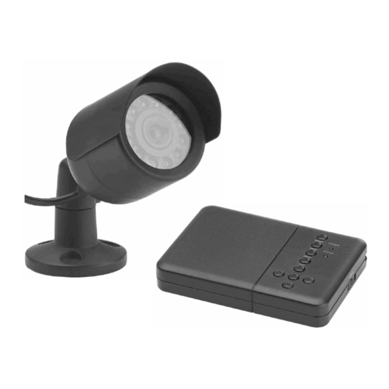
- Page 1 Wired Colour Camera(s) and 2 Channel Digital Video Recorder (DVR) CCTV CWK2 / CWK3 Installation and Operating Instructions These instructions should be retained in a safe place for future reference.
-
Page 2: Table Of Contents
CONTENTS 1 INTRODUCTION 7 SYSTEM CONFIGURATION 2 KIT CONTENTS 8 TROUBLE SHOOTING 3 FEATURES 9 TECHNICAL SPECIFICATION 4 INSTALLATION 10 ACCESSORIES IN THE RANGE System Connection Camera(s) Installation 11 DISPOSAL – RECYCLING INSTRUCTIONS 5 PANEL INTRODUCTION 12 GUARANTEE AND 6 OPERATION CUSTOMER HELPLINE Keys - Functions Changing Between Real Time... -
Page 3: Introduction
INTRODUCTION Section 1 The Response 2 Channel DVR Camera(s) Kit is a monitoring system designed to capture photos or 10 second video clips of any motion viewed by the camera(s) and store them in memory. It allows up to 2 wired cameras to connect to it. The wired cameras are colour, weatherproof and suitable for day / night use. -
Page 4: Kit Contents
KIT CONTENTS Section 2 CWK2: 1 x 2 Channel DVR unit 1 x Wired Colour Camera 1 x 10m extension cable 1 x DIN to RCA adaptor lead assembly 1 x Video output to TV cable (1m) 1 x Power supply adaptor for DVR unit (12V/1.2A) -
Page 5: Features
FEATURES Section 3 2 channel video imput / 1 channel video output SD card technology Photos recorded in JPG format / video recorded in AVI format Motion detection Preset NTSC / PAL system input Time and date stamp Picture in picture display (view one camera channel in another camera channel) -
Page 6: Installation
INSTALLATION Section 4 4.1 System Connection TV / MONITOR CAMERAS Video Signal to Input Extension Cable(s) Camera Power Supply Adaptor Not used In this model Camera Power Supply Adaptor DVR Power DIN IN Supply Adaptor VIDEO IN 2 VIDEO IN 2 POWER IN VIDEO OUT Key to DIN plug colours:... -
Page 7: Camera(S) Installation
4.2 Camera(s) Installation 1. Remove the bracket from the camera by unscrewing it from the main body as shown below: Unscrew this washer nut to loosen Camera body from the bracket and unscrew Camera Camera body position adjustment nut 2. Use the base of the camera’s bracket to mark out the 3 mounting holes on the chosen surface. - Page 8 Insert the SD card into the DVR if not already fitted. 10. Turn ON the DVR using the power switch. 11. Tune your TV to auxiliary (AUX), A/V or video mode to view the camera. (Note: Refer to your TV/VCR/DVR’s owner’s manual for setting this up). 12.
-
Page 9: Panel Introduction
PANEL INTRODUCTION Section 5 MODE POWER SNAP STATUS MENU DISP Key to controls: 1. DIN IN 6. DISP (Display) Key (2 channel video input; Up Key 2 channel output; 12VDC/1.2A Power IN) Right Key 2. MODE Key Enter Key 3. SNAP Key Down Key (Take Photo or Record) Left Key... -
Page 10: Operation
OPERATION Section 6 6.1 Keys - Functions Reference Real time mode Play back mode Setup menu to diagram (Live viewing) Mode Switch to play Switch to real back mode time mode Menu Setup menu Delete files menu Exit setup menu appears (for video clips, the Menu key only functions at the... -
Page 11: Changing Between Real Time Viewing And Playback Mode
Motion detect Move up to a photo / Move the motion ON/OFF (Indicated video clip. Before detect area / on the top left of playing back a file, sensitivity up the TV/monitor by the on screen display when adjusting an ‘eye’ sign) details can be removed or restored Down... -
Page 12: Menu Icons Definition
6.5 Menu Icons Definition: Setup Screen Date Time Setup Advance Setup Motion Detect On or Off Quit Menu Select Photo or Video Advance Setup Select TV System, Select Image Quality NTSC or PAL High or Low Motion Detect Motion Detect Count Area Setting Motion Detect Motion Detect... -
Page 13: Date/Time Setup
6.6.1 Date/Time Setup Use the left / right key to select the ‘Time Setup’ icon and press enter. Use the left / right key to select the date or time. Use the up / down key to set the correct digit. Press enter to confirm settings. -
Page 14: Playing Back Recorded Photos / Video Clips
1.12 Use the left / right key to move to the ‘Motion Detect Interval’ icon. For photo capture format mode only, this is used to set the interval break in seconds between each capture (for example, if set to 5, then after the first trigger, it would take 5 seconds for the DVR to trigger again). -
Page 15: Memory Overwrite Indication
3. Use the left / right key to move back or forward to an image or video clip. 4. To play back a video, press the Down key in full screen mode to play the video file 5. In full screen view, press the Up key to turn ON / OFF the on screen display information (date, time, capture number, etc). -
Page 16: System Configuration
SYSTEM CONFIGURATION Section 7 Preview Mode Camera 1 Camera 2 Camera 1 (Camera 2) Camera 2 (Camera 2) MENU Date Time Set up Motion Detect On or Off Select Photo or Video Motion Detecting Motion Detect Advance Set up Area Setting Settings Quit Menu Motion Detecting... -
Page 17: Trouble Shooting
TROUBLE SHOOTING Section 8 PROBLEM SOLUTION No camera picture The power supply adaptor for the DVR or camera(s) is not plugged in. Check all video cable connections between the camera(s) and DVR. The TV is not tuned to view the correct channel. Poor picture quality Clean the camera lens. -
Page 18: Technical Specification
TECHNICAL SPECIFICATION Section 9 ITEM 2 CHANNEL DVR Video format PAL / NTSC Video input 2 channel (NTSC / PAL) (RCA) Video output 1 channel (NTSC / PAL) Composite video output Video display Single picture or picture in picture display Display resolution JPEG VGA: 640 x 480 AVI QVGA:... - Page 19 ITEM WIRED CAMERA Image sensor 1/4” colour CMOS Video format PAL / NTSC Pixel resolution PAL: 628 (H) x 582 (V) NTSC: 510 (H) x 492 (V) Horizontal resolution 380 TV lines Minimum illumination 0 lux when the IR lamps are turned on Viewing angle 50°...
-
Page 20: Accessories In The Range
ACCESSORIES IN THE RANGE Section 10 There are a range of accessories available in the Response CCTV product range to expand your system: CWK1 Wired Colour Camera CCTV Kit LCD Screen for Wireless / Wired CCTV Kits CWFK1 Wireless Colour Camera CCTV Kit... -
Page 21: Disposal - Recycling Instructions
DISPOSAL – RECYCLING INSTRUCTIONS Section 12 Directive (2002/96/EC) This product is classified by the Waste Electrical or Electronic Equipment (WEEE) Directive. It should not be disposed of with other household or commercial waste. At the end of its useful life the packaging and product should be disposed of via a suitable recycling centre. -
Page 22: Customer Helpline
1. Proof of purchase. 2. A full description of the fault. 3. All relevant batteries (disconnected). Response is a trademark of Novar ED&S. CUSTOMER HELPLINE Most issues can be solved over the phone in a few minutes. Please contact our Helpline Team on the number below for any... - Page 24 Novar Electrical Devices and Systems Limited. (A Honeywell Company) The Arnold Centre, Paycocke Road, Basildon, Essex SS14 3EA. UK www.friedland.co.uk © Novar Electrical Devices and Systems Limited. 2009 50043918 Rev.A...
Need help?
Do you have a question about the CWK2 and is the answer not in the manual?
Questions and answers